Design Revision History
www.ti.com
18
SPRUIM4B–December 2018–Revised May 2020
Submit Documentation Feedback
Copyright © 2018–2020, Texas Instruments Incorporated
xWR1843 Evaluation Module (xWR1843BOOST) Single-Chip mmWave
Sensing Solution
3.2.2 Power Supply Optimization
For best transient supply settling at the start of the chirp, the [idle time + TX start time] can be set to a
value < 10 µsec. In this configuration, the AWR firmware keeps some of the RF blocks ON between the
chirps. For idle time + Tx start time > 10 µsec, the blocks are turned off for power saving. In this case, TI
recommends adding an additional resistive load on the 1-V LDO oputput; the available R83 pad can be
used for this purpose. The value of the resistance can be between 10 to 30 Ω, depending on the idle time
setting. The other option is to disable the inter-chirp power save feature of the AWR device using the
AWR DYNAMICPOWERSAVE CONF SET SB API.
The LC filter on the 1-V and 1.8-V supplies is used to filter the 4-Mhz ripple from the switcher. There could
be small ringing behavior at the point of transient load change. If this is impacting the RX sampled data,
the ADC start time can be increased to a point where the supply is settled within 5%, or the inductance
value can be reduced to reduce the ringing (which may come at the expense or poorer 4-Mhz filtering).
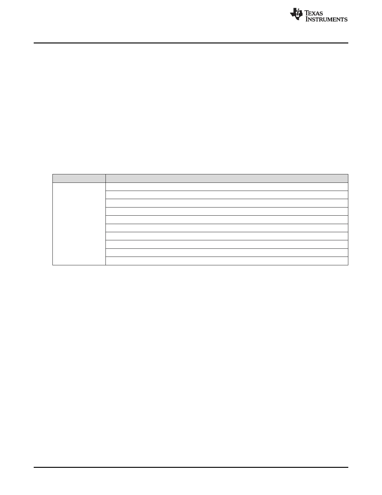
4 Design Revision History
Table 6. Design Revision History
PCB Revision Change Description
Rev C Increased LDO output cap to 47 µF
Added two optional 100-µF LDO output caps
Added 10-µF cap to LDO output
Added test pad to LDO PG pin
Connected LDO DNC pads to GND for thermal performance
Added optional bleeed resistor on LDO output
Changed 1-V filtering to BLM18 inductor
Added 22-µF caps to 1-V, 1.24-C, and 1.8-V LC filters
Added 10-µF cpas to 3.3-V and 1.24-V LC filters
Added additional 10-µF caps to 1-V LC fitlers
5 Mechanical Mounting of PCB
The field of view of the radar sensor is orthogonal to the PCB. To enable easy measurements on the
sensing objects on the horizontal plane, the PCB can be mounted vertically. The L-brackets provided with
the xWR1843 EVM kit, along with the screws and nuts help in the vertical mounting of the EVM. Figure 23
shows how the L-brackets can be assembled.

 Loading...


