www.ti.com
Hardware
9
SPRUIM4B–December 2018–Revised May 2020
Submit Documentation Feedback
Copyright © 2018–2020, Texas Instruments Incorporated
xWR1843 Evaluation Module (xWR1843BOOST) Single-Chip mmWave
Sensing Solution
2.4 PC Connection
The connectivity is provided through the micro USB connector over the onboard XDS110
(TM4C1294NCPDT) emulator. This connection provides the following interfaces to the PC:
• JTAG for Code Composer Studio™ (CCS) connectivity
• UART1 for flashing the onboard serial flash, downloading FW through Radar Studio, and getting
application data sent through the UART
• MSS logger UART (can be used to get MSS code logs on the PC)
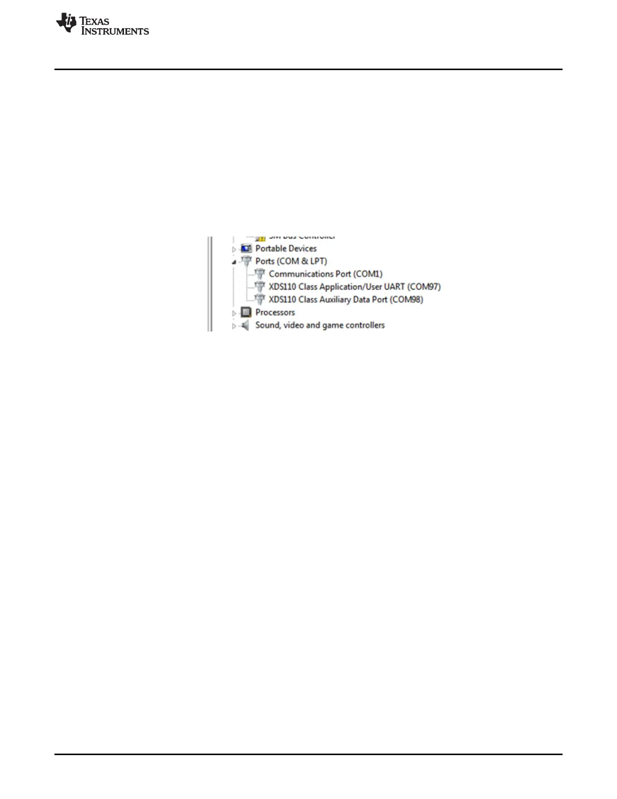
When the USB is connected to the PC, the device manager should recognize the following COM ports,
shown in Figure 8:
• XDS110 Class Application/User UART – UART1 port
• XDS110 Class Auxiliary Data Port – MSS logger port
Figure 8. COM Ports
If Windows
®
is unable to recognize the COM ports, users must install the EMU pack available at XDS
Emulation Software Package.
2.5 Connecting the BoosterPack to the DCA1000
The BoosterPack can be connected to the DCA1000 FGPA platform to allow for LVDS streaming over
Ethernet. For detailed information on how to capture LVDS data using the DCA1000, see the following
resources.
• DCA1000 Product Page
• DCA1000 User's Guide
• DCA1000 Training Video