Hardware
www.ti.com
8
SPRUIM4B–December 2018–Revised May 2020
Submit Documentation Feedback
Copyright © 2018–2020, Texas Instruments Incorporated
xWR1843 Evaluation Module (xWR1843BOOST) Single-Chip mmWave
Sensing Solution
Table 3. J1 Connector Pin (continued)
Pin Number Description Pin Number Description
43 TRACE_DATA12 44 LVDS_CLKP
45 TRACE_DATA13 46 LVDS_CLKM
47 TRACE_DATA14 48 GND
49 TRACE_DATA15 50 LVDS_1P
51 I2C_SDA 52 LVDS_1M
53 I2C_SCL 54 GND
55 RS232RX (Rx into AWR device) 56 LVDS_0P
57 RS232TX (Tx from AWR device) 58 LVDS_0M
59 nRESET 60 GND
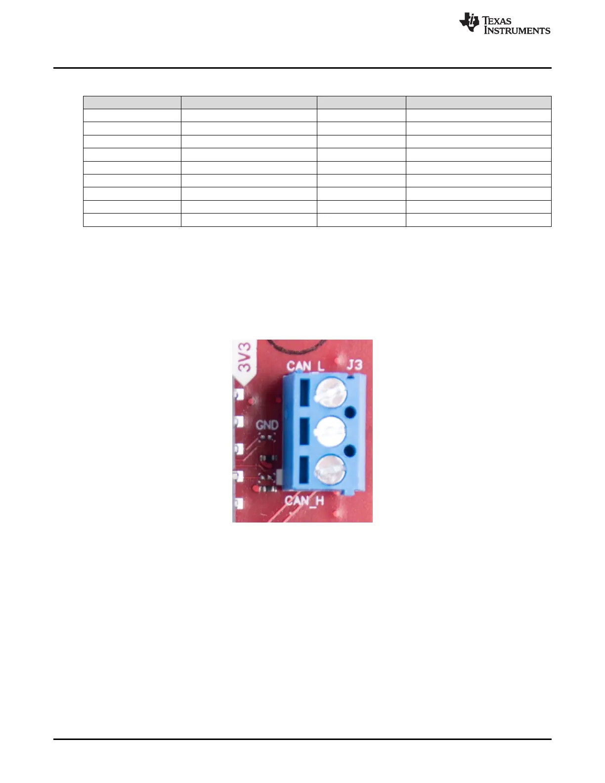
2.3.3 CAN Interface Connector
The J3 connector provides the CAN_L and CAN_H signals from the onboard CAND-FD transceiver
(TCAN1042HGVDRQ1). These signals can be directly wired to the CAN bus.
Because the digital CAN signals (Tx and Rx) are muxed with the SPI interface signals on the AWR device,
one of the two paths must be selected. This is done by placing the switch S2 on the "CAN" position.
Figure 7 shows the CAN connector.
Figure 7. CAN Connector

 Loading...


