www.ti.com
Hardware
13
SPRUIM4B–December 2018–Revised May 2020
Submit Documentation Feedback
Copyright © 2018–2020, Texas Instruments Incorporated
xWR1843 Evaluation Module (xWR1843BOOST) Single-Chip mmWave
Sensing Solution
NOTE: The xWR1843BOOST has been testing in the 76- to 77-GHz band and in the 77- to 81-GHz
band across the temperature range of –20°C to 60°C.
NOTE: During operation, a minimum separation distance of 5 centimeters should be maintained
between the user and the EVM.
2.8 Jumpers, Switches, and LEDs
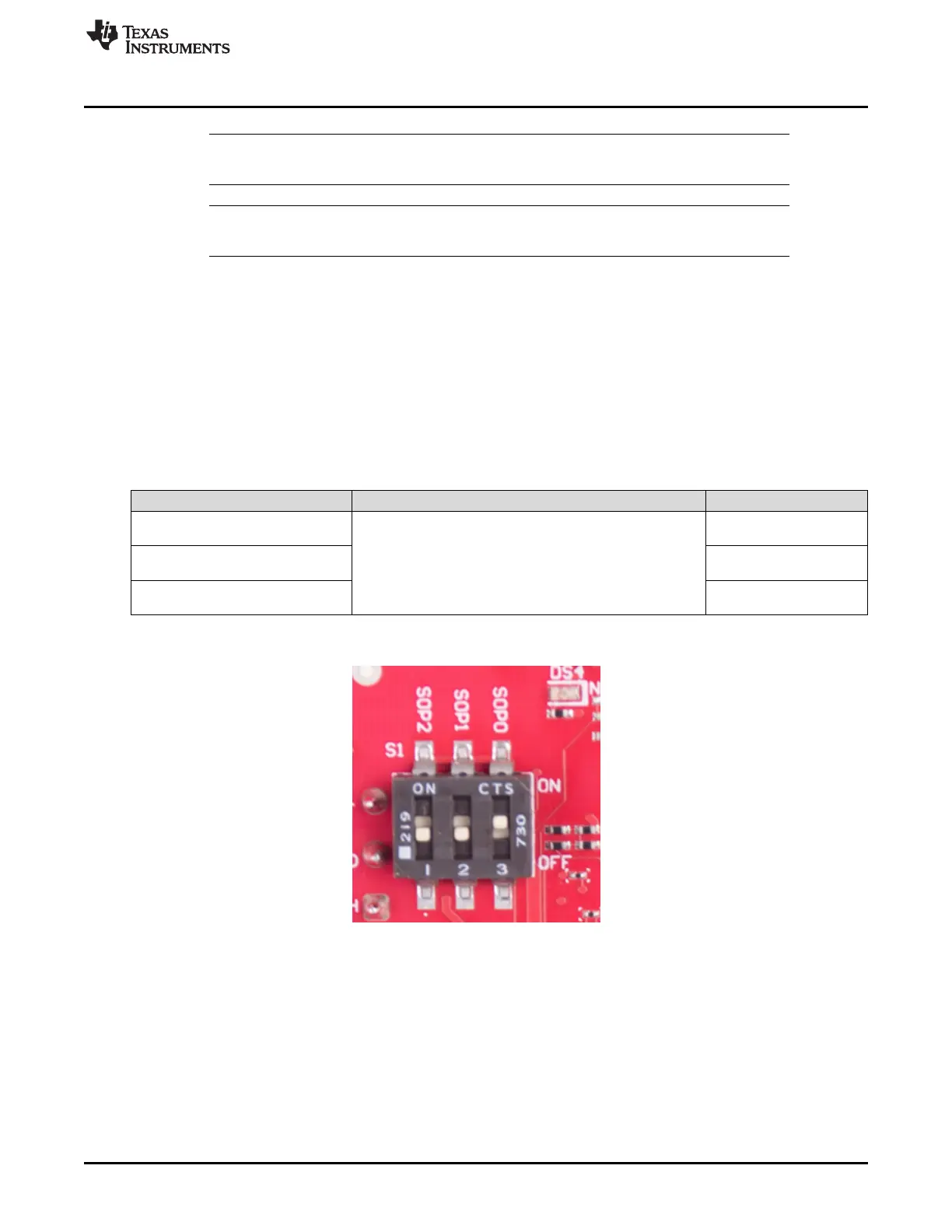
2.8.1 Sense-on-Power (SOP) Jumpers
The xWR1843 device can be set to operate in three different modes based on the state of the SOP lines.
These lines are sensed only during boot up of the AWR device. The state of the device is detailed by
Table 4.
The SOP mode is set using switch S1. When the switch position is 'ON', this refers to a 1. When the
switch position is 'OFF', this refers to a 0.
Table 4. SOP Switch Information
Reference Usage Comments
SOP 2
SOP[2:0]
101 (SOP mode 5) = flash
programming
SOP 1
001 (SOP mode 4) =
functional mode
SOP 0
011 (SOP mode 2) =
debug mode
Figure 13 shows the SOP jumpers.
Figure 13. SOP Jumpers

 Loading...


