www.ti.com
Hardware
7
SPRUIM4B–December 2018–Revised May 2020
Submit Documentation Feedback
Copyright © 2018–2020, Texas Instruments Incorporated
xWR1843 Evaluation Module (xWR1843BOOST) Single-Chip mmWave Sensing
Solution
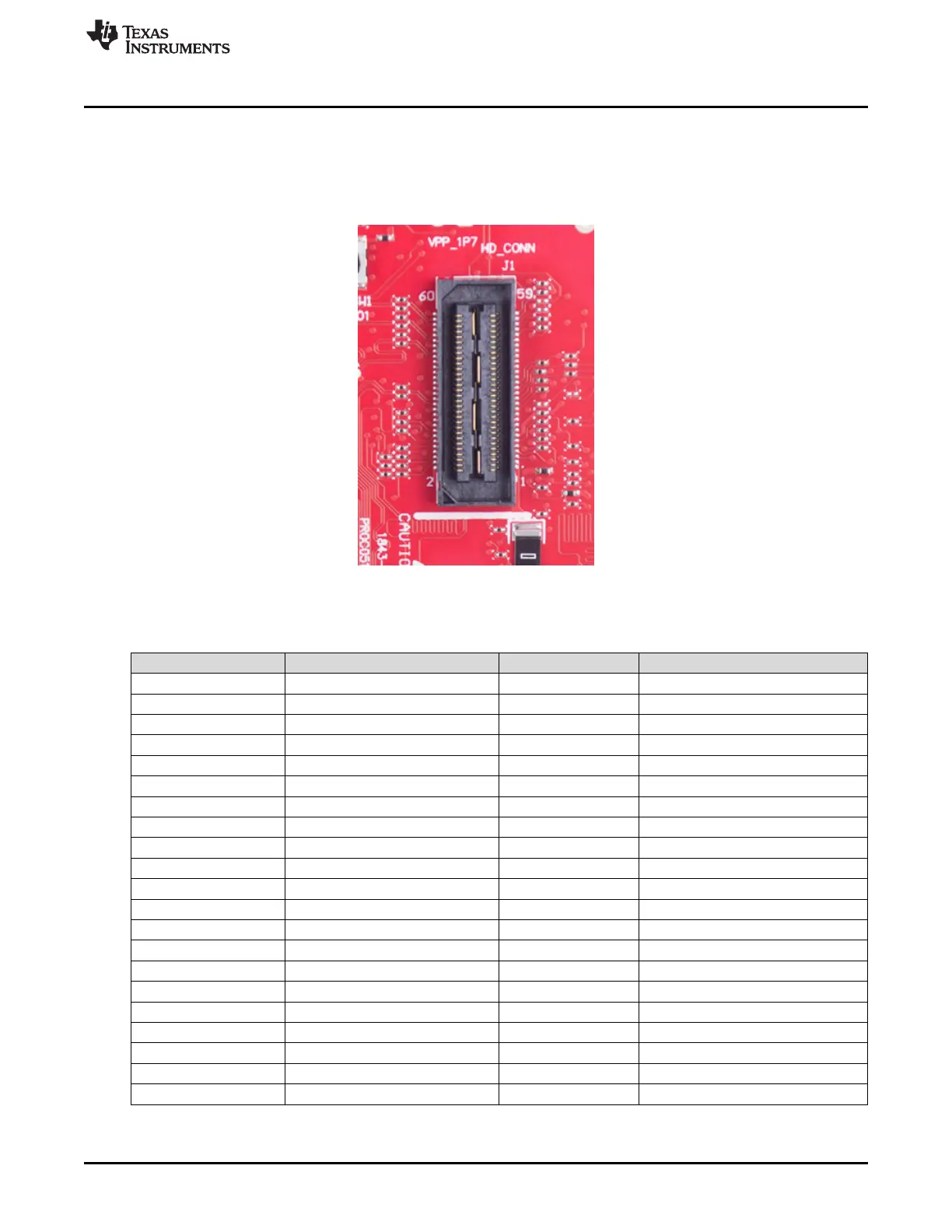
2.3.2 60-Pin HD Connector
The 60-pin HD connector provides the high speed LVDS data, control signals (SPI, UART, I
2
C, NRST,
NERR, SOPs) and JTAG debug signals. The connector can be connected to the MMWAVE-DEVPACK
board to further get to the standard TSW1400 EVM. Figure 6 shows the HD connector, and Table 3
provides the connector information.
Figure 6. HD Connector
(1)
Indicates the state of the onboard VIO supply for the AWR device coming from the onboard PMIC. A HIGH on the PGOOD
signal (3.3 V) indicates the supply is stable. Because the I/Os are not failsafe, the MCU must not drive any I/O signals to the
AWR device before this I/O supply is stable to avoid leakage current into the I/Os.
Table 3. J1 Connector Pin
Pin Number Description Pin Number Description
1 5V 2 5V
3 5V 4 TDO
5 TDI 6 TCK
7 SPI_CS 8 TMS
9 SPI_CLK 10 HOSTINT
11 SPI_MOSI 12 SPI_MISO
13 PGOOD (onboard VIO)
(1)
14 NERROUT
15 DMM_CLK 16 SYNC_IN
17 DMM_SYNC 18 GND
19 TRACE_DATA0 20 NC
21 TRACE_DATA1 22 NC
23 TRACE_DATA2 24 GND
25 TRACE_DATA3 26 LVDS_FRCLKP
27 TRACE_DATA4 28 LVDS_FRCLKM
29 TRACE_DATA5 30 GND
31 TRACE_DATA6 32 NC
33 TRACE_DATA7 34 NC
35 TRACE_DATA8 36 GND
37 TRACE_DATA9 38 NC
39 TRACE_DATA10 40 NC
41 TRACE_DATA11 42 GND

 Loading...


