2007.03.07 Flow2 stairlift Tab 06: Systematic fault finding
www.ThyssenKruppAccessibility.nl 11
Flow subsystems
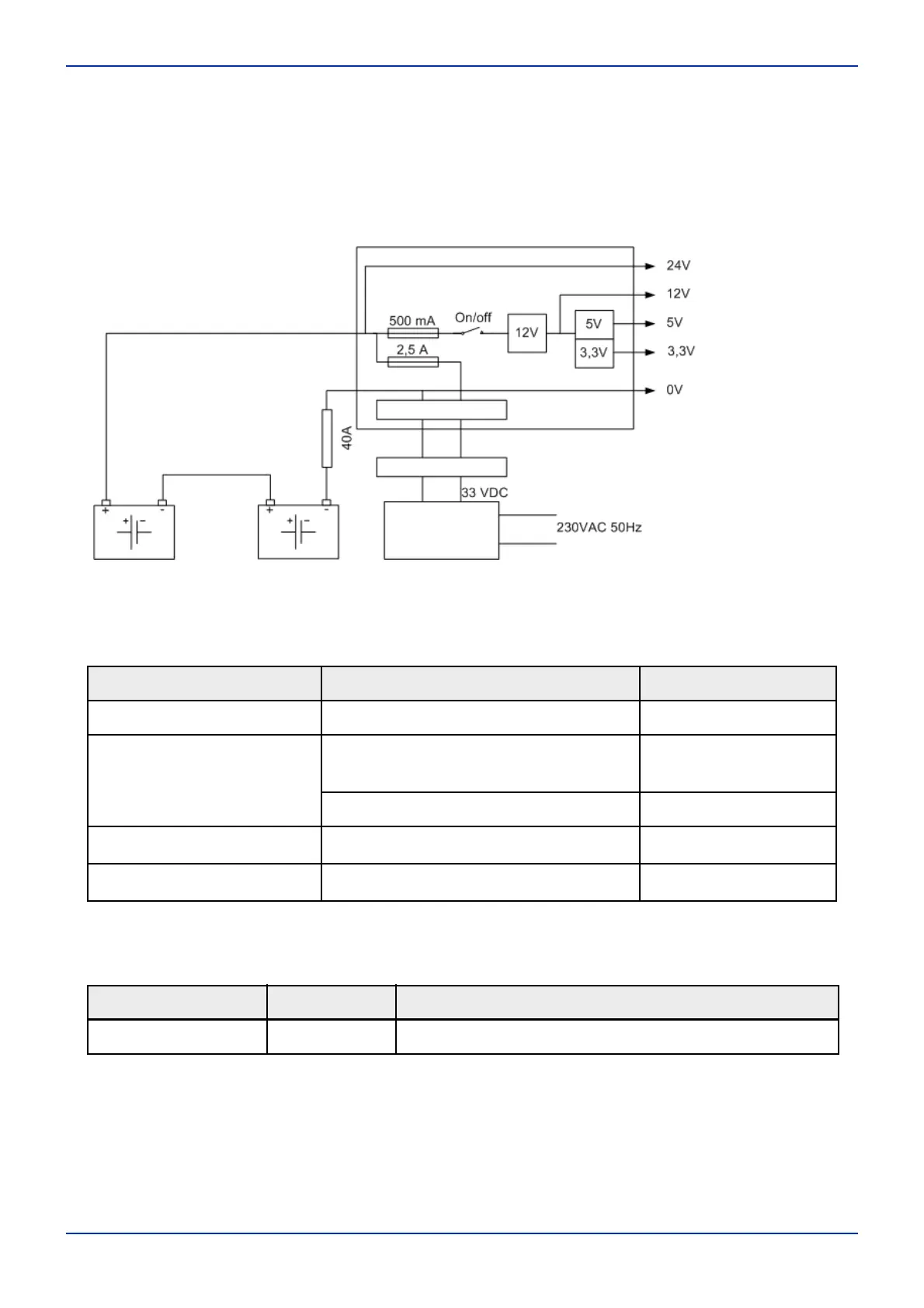
3.1 The power supply system
If the stairlift does not work, a malfunction may have occurred in the stairlift power supply.
The following voltages can/must be measured.
The green LED on the power board shows the status of the power supply. All other LEDs can of
course be used as an indication of the presence of the supply voltage.
Component Measurement point Voltage (V)
Main board Connector J4 12 Vdc
Power module 3V3, 5V and 12V, as indicated on the
printed circuit board
3V3, 5V and 12V
Between the “plus” and “min” Battery voltage
Transformer Input terminals (U
in
) 220 +/- 10% (VAC)
Transformer Output terminals (U
uit
) 33 +/- 10% (VDC)
Component LED Meaning
Power module Green LED - Lit when all output voltages are present.
Fuse 40 A
Transformer/
rectifier
Charging contact
Charging circuit
Power module
Glass fuses
Fig. 3-1 The power supply
 Loading...