14
9.2. How to Connect Input Signals
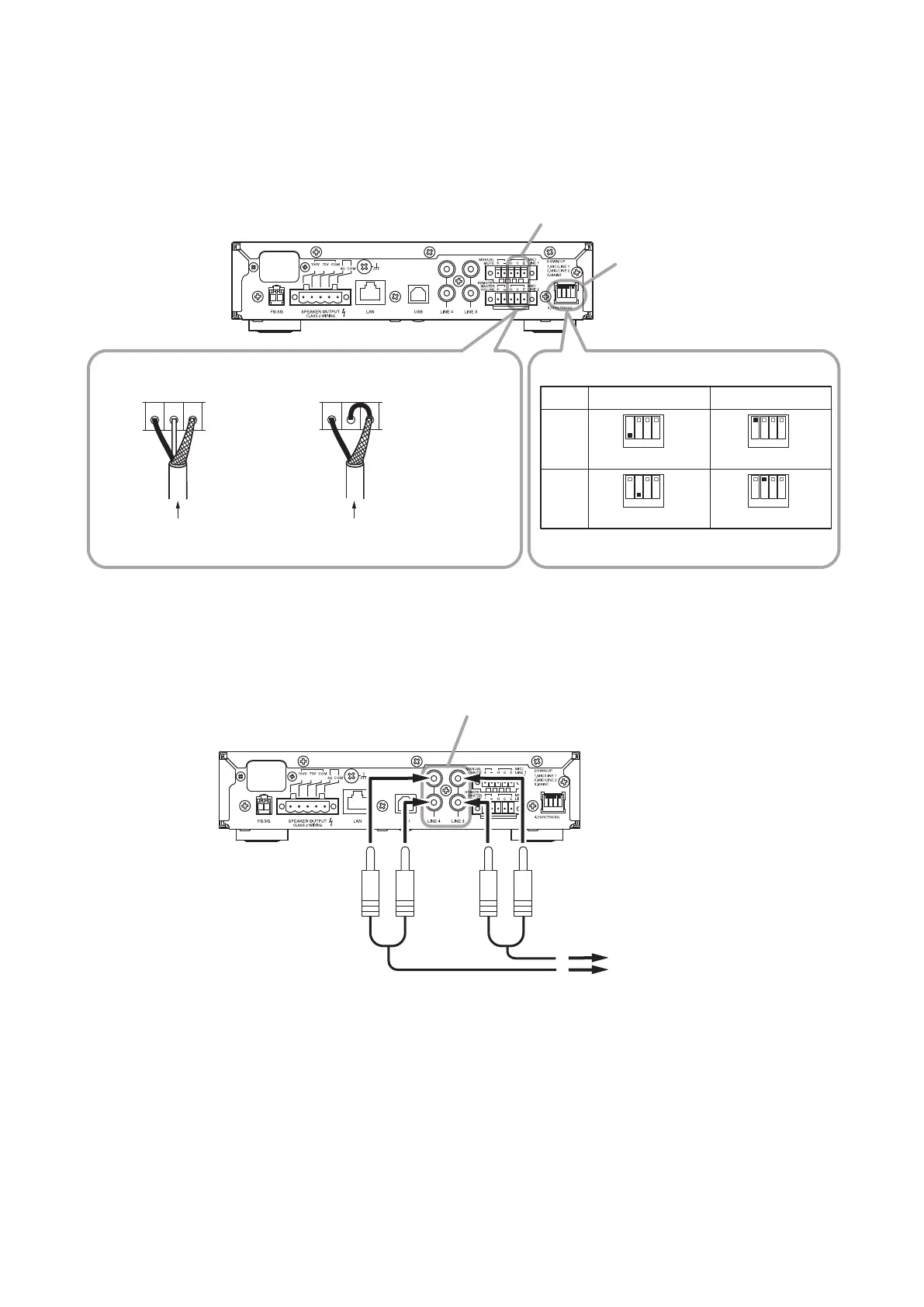
9.2.1. Inputs 1 and 2 connections
Use the supplied Small type removable terminal plug (5 pins) for connection. Inputs 1 and 2 can be set to MIC
or LINE input.
When setting, use Switch 1 of the DIP switch for the Input 1 connection and Switch 2 for the Input 2 connection.
1 2 3 4
C EH
C EH
1 2 3 4
1 2 3 4
1 2 3 4
1 2 3 4
A-5006/5012
1 : DOWN
2 : DOWN
1 : UP
2 : UP
MIC/LINE input terminals (1, 2)
DIP switch
[Using a 2-core shielded wire] [Using a single-core shielded wire]
Short terminals
C and E.
From microphone or
external playing equipment
From microphone or
external playing equipment
MIC Input LINE Input
Input 1
Input 2
Switches 1 and 2 are both factory-preset to the
UP position.
[DIP switch settings]
9.2.2. Inputs 3 and 4 connections
Inputs 3 and 4 are intended exclusively for LINE input.
When connecting a monaural sound source, connect the L line.
1 2 3 4
A-5006/5012
To playing equipment
LINE input terminals (3, 4)
–20 dB, 10 kΩ, unbalanced
RCA pin jack
Note: L and R line signals are mixed inside the unit.
 Loading...