9
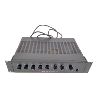
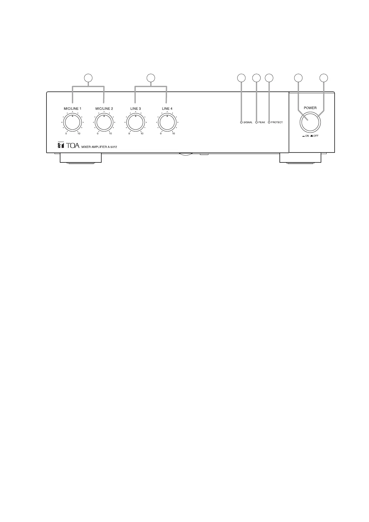
7. NOMENCLATURE AND FUNCTIONS
[Front]
1. Power switch
Turns unit power ON and OFF with each press of
the switch.
Note
When re-using contents set with the A-5000 PC
Setting software, be sure to save the contents to
the preset memory before turning the power OFF.
The set contents will be lost if the power is switched
off before Save procedure is completed.
For details, please read the software instruction
manual on the supplied CD.
2. Power indicator (Green)
Lights green when power is switched ON, and
extinguishes when power is switched OFF.
3. MIC/LINE input volume controls (1, 2)
Adjusts the sound volume of MIC/LINE Input 1 or 2.
4. LINE input volume controls (3, 4)
Adjusts the sound volume of LINE Input 3 or 4.
5. Signal indicator (Green)
Lights when the sound volume of any signal input
exceeds the specied level (–20 dB from the rated
output level).
6. Peak indicator (Red)
Lights when the sound volume of any signal input
reaches a high level (–3 dB from the rated output
level).
Note
Adjust the sound volume to prevent this indicator
from continually lighting. If it remains lit, sound
output could be distorted.
7. Failure indicator (Red)
Lights when the unit’s protection circuitry is in
operation (when a failure is detected) or when the
fan fails.
Note
When this indicator lights, both the Signal Indicator
(5) and Peak Indicator (6) will extinguish.
76 253 4 1
The gure shows the A-5012.
 Loading...