2
09.16
-
-
-
-
RV
RVR
TOR.089.--.M.4L-PL
W celu zapewnienia oczyszcza-
nia obszaru między wirnikiem
a pokrywą z jednej strony oraz
między wirnikiem a korpusem
śluzy z drugiej strony umiesz-
czono (w pokrywie i korpusie)
otwory gwintowane, do których
podłączane są przewody sprężo-
nego powietrza (patrz poniższe
rysunki). System taki pozwala
unikać formowania się osadów,
mogących spowodować zabloko-
wanie wirnika. Zasada działania
jest bardzo prosta: wtłaczane
pod niezbyt wysokim ciśnieniem
powietrze zapobiega osadzaniu
się materiału w wymienionych
wyżej miejscach, wydmuchując
go do otworu wylotowego w dolnej
części śluzy celkowej. W modelu
RV02 otwór do podłączania sprę-
żonego powietrza przewidziano
tylko na pokrywie.
W poniższej tabeli zestawiono
wymiary otworu gwintowanego
(przyłącza sprężonego powietrza) w
zależności od wielkości śluzy oraz ci-
śnienie wymagane do prawidłowego
działania mechanizmu czyszczenia.
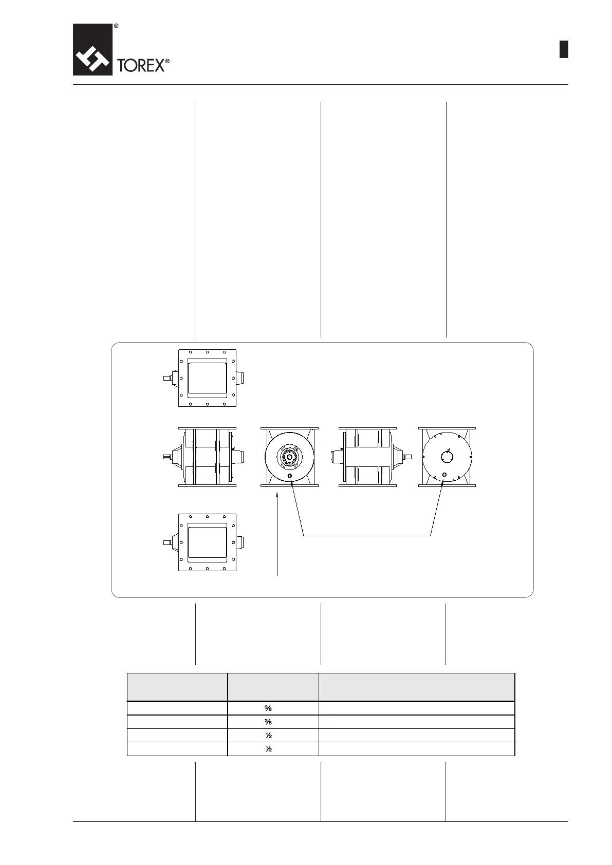
Front - Vorderseite - Face - Przód
Back- Hinterseite- Dos - Tył
Air connections - Luftanschlüsse
Connexions air - Przyłącza spręż. powietrza
To clean the area between the
rotor and the lid on one side,
and between the rotor and the
casing on the opposite side,
some threaded holes have been
provided on the lid and on the
casing of the rotor valve for con-
nection to compressed air (see
diagram below). This system
avoids the formation of deposits
that could cause the valve to
block. The operating principle
is very simple: the air entering at
rather low pressure, prevents the
material from penetrating into the
above-mentioned spaces where
deposits might be formed, and it
also pushes the material towards
the outlet provided in the lower
part of the valve.
On the RV02 a hole is provided
only on the lid.
The table below shows the dimen-
sions of the threaded hole of every
machine for the connection to a
pneumatic link, and the operat-
ing pressure required for correct
cleaning.
In der nachstehenden Tabelle
sind, je nach Maschinenmodell,
die Maße der Gewindebohrung
für den Anschluss einer Druckluft-
leitung sowie der Betriebsdruck
für eine korrekte Reinigung an-
gegeben.
Zur Reinigung des Bereichs
zwischen Zellenrad und End-
schild auf der einen Seite und
Zellenrad und Gehäuse auf der
gegenüberliegenden Seite sind
am Endschild und am Gehäuse
der Schleuse Gewindebohrungen
für den Anschluss von Druck-
luftleitungen vorgesehen (siehe
nachstehende Zeichnung). Mit
diesem System lassen sich Ver-
krustungen vermeiden, die eine
Blockierung der Schleusen zur
Folge haben können. Das Funk-
tionsprinzip ist äußerst einfach:
Die mit ziemlich niedrigem Druck
einströmende Luft verhindert,
daß sich das in die vorgenann-
ten Toträume eingedrungene
Material absetzt und bläst es zur
Auslauföffnung am unteren Teil
der Schleuse. Beim Modell RV02
ist die Bohrung nur am Endschild
vorgesehen.
Pour pouvoir effectuer le net-
toyage dans la zone comprise
entre le rotor et le couvercle d’une
part, et entre le rotor et le corps
dans la partie opposée, sur le
corps de la vanne rotative il a été
prévu des trous letés pour le rac-
cordement à de air comprimé (voir
dessin ci-dessous). Ce système
permet d’éviter les incrustations
qui pourraient provoquer le blo-
cage de la vanne.
Le principe de fonctionnement
est très simple : l’air, qui entre à
une pression plutôt basse, évite
que le produit pénètre dans les
espaces décrit ci-dessus pour
former un sédiment et le chasse
vers l’évacuation dans la partie
inférieure de la vanne.
Pour l’ RV02 le trou est prévu
soulement sue le couvercle.
Dans le tableau ci-dessous sont
indiquées les dimensions du trou
leté de chaque machine pour le
raccordement pneumatique et la
pression de service pour obtenir
un nettoyage correct.
Not present on the RV02 - Fehlt auf RV02
Absent en RV02 - Brak w mod. RV02
PNEUMATICCONNECTIONS
LUFTANSCHLUSSPNEUMATISCHE
RACCORDEMENTSPNEUMATIQUE
POŁĄCZENIAPNEUMATYCZNE
Machine - Ma schine
Machine - Maszyna
Hole - Bohrung
Trou - Otwór
Operating pressure - Druckbetrieb
Pression de service - Ciśnienie robocze
RV - RVR 02
a
"G 0.2 - 0.4 bar
RV - RVR 05
a
"G 0.2 - 0.4 bar
RV - RVR 10
2
"G 0.2 - 0.4 bar
RV - RVR 20
2
"G 0.2 - 0.4 bar
Instalator winien zadbać o za-
mocowanie (podłączenie) prze-
wodów sprężonego powietrza i
zabezpieczyć układ przed przy-
padkowym odłączeniem sekcji
przewodów.
It is the installer’s responsibility
to x the compressed air hoses
and provide for protection from
sudden detachment of a section
of the piping.
Der Installateur wird dafür sor-
gen, die Druckluftschläuche zu
befestigen und die erforderlichen
Schutzmaßnahmen gegen das
unvorhergesehene Abtrennen
einer Leitungsstrecke zu treffen.
L’installateur doit se charger de
fixer correctement les tuyaux
flexibles de l’air comprimé et
prévoir les protections contre le
détachement soudain d’un tron-
çon de tuyauterie.
16
 Loading...