g017590
Figure5
1.Cableties
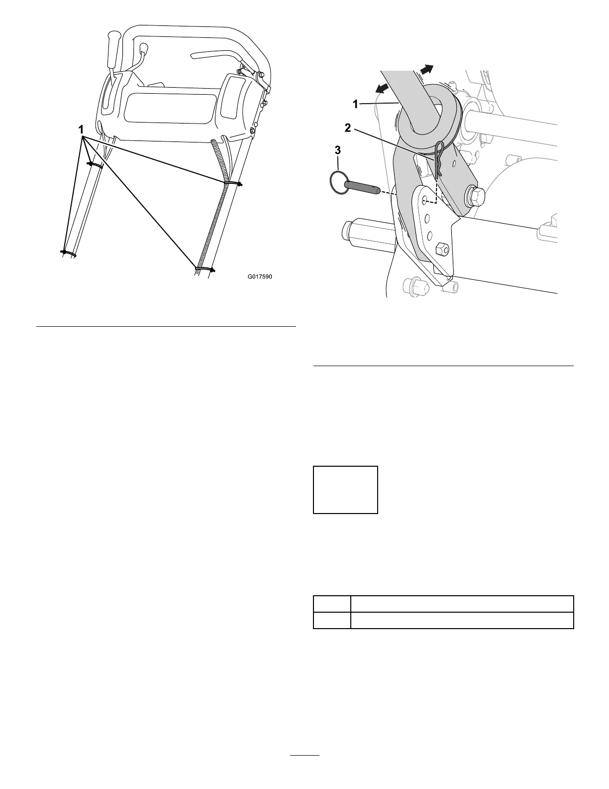
AdjustingtheHandle
RefertoFigure6forthisprocedure.
g240512
Figure6
1.Handle3.Ringpin
2.Hairpincotter
1.Removethehairpincottersfromtheringpinson
eachsideofthemachine.
2.Whilesupportingthehandle,removethering
pinsfromeachsideandraiseorlowerthe
handletothedesiredoperatingposition.
3.Installtheringpinsandhairpincotters.
2
Installingthe
Transport-WheelShafts
Partsneededforthisprocedure:
1
Rightwheelshaft
1
Leftwheelshaft
Procedure
1.Pushthekickstanddownwithyourfootandpull
uponthehandletosupportthemachineonthe
kickstand.
2.Applythread-lockingadhesivetothethreadsof
thewheelshafts.
9
 Loading...


