Note:Donotrunthemachinewiththebattery
disconnected,electricaldamagemayoccur.
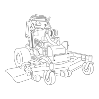
Figure52
1.PositiveBatteryPost
3.Red(+)ChargerLead
2.NegativeBatteryPost
4.Black(-)ChargerLead
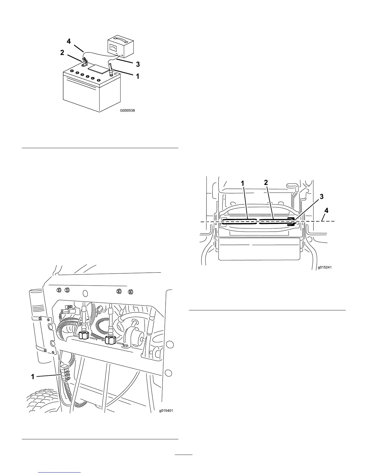
ServicingtheFuses
Theelectricalsystemisprotectedbyfuses.Itrequires
nomaintenance.Ifafuseblows,checkthecomponent
orcircuitforamalfunctionorshort.
1.Releasethecushionfromtherearofthemachine.
2.Pulloutonthefusetoremoveorreplaceit
(Figure53).
3.Installthecoverunderthecusion.
Note:Ensurethecorrectsizefuseisinstallwiththe
correctwirecolorasshowninFigure53.
Figure53
1.Controls
DriveSystem
Maintenance
AdjustingtheTracking
Note:Determinetheleftandrightsidesofthemachine
fromthenormaloperatingposition.
1.Pushbothcontrolleversforwardthesamedistance.
2.Checkifthemachinepullstooneside.Ifitdoes,
stopthemachineandsettheparkingbrake.
3.Releasethecushionfromtherearofthemachine.
4.Liftandremovethecablelocksecuringthecable
adjustingnuts(
Figure55).
5.Rotatetherightcableadjustmenttopositionthe
rightmotioncontrolinthecenterofthecontrol
panelneutrallockslot(
Figure55).
Figure54
1.Leftmotioncontrollever
3.Neutrallockedposition
2.Rightmotioncontrollever4.Alignthecontrollevers
fronttoback
6.Rotatetheleftcableadjustmenttomatchtheleft
wheelspeedtothepreviouslysetrightwheelspeed.
Adjustinquarter-turnincrementsuntilthemachine
tracksstraight.
Note:Onlyadjusttheleftcabletomatchtheleft
wheelspeedtotherightwheelspeed.Donotadjust
therightwheelspeedasthiswillpositiontheright
motioncontrolleveroutofthecenterforthecontrol
panelneutrallockslot.
40

 Loading...