AssemblingtheFrontRoller
1.Presstherstbearingintotherollerhousing
(Figure126).Pressontheouterraceonlyor
equallyontheinnerandouterrace.
2.Insertthespacer(Figure126).
3.Pressthesecondbearingintotherollerhousing
(Figure126).Pressingequallyontheinner
andouterraceuntiltheinnerracecontactsthe
spacer.
4.Installtherollerassemblyintothecutting-unit
frame.
5.Verifythatthereisnomorethana1.5mm(0.060
inch)gapbetweenrollerassemblyandtheroller
mountbracketsofthecutting-unitframe.Ifthere
isagapover1.5mm(0.060inch),installenough
5/8-inchdiameterwasherstotakeuptheslop.
Important:Securingtherollerassembly
withagaplargerthan1.5mm(0.060inch)
createsasideloadonthebearingandcan
leadtoprematurebearingfailure
6.Torquethemountingboltto108N∙m(80ft-lb).
BladeMaintenance
BladeSafety
•Inspectthebladeperiodicallyforwearordamage.
•Usecarewhencheckingtheblades.Wrapthe
bladesorweargloves,andusecautionwhen
servicingtheblades.Onlyreplaceorsharpenthe
blades;neverstraightenorweldthem.
•Onmulti-bladedmachines,takecareasrotating
onebladecancauseotherbladestorotate.
ServicingtheBladePlane
Thecuttingunitcomesfromthefactorypresetat5
cm(2inches)heightofcutandbladerakeof7.9mm
(0.310inch).Theleftandrightheightsarealsopreset
towithin±0.7mm(0.030inch)oftheother.
Thecuttingunitisdesignedtowithstandblade
impactswithoutdeformationofthechamber.Ifthe
bladestrikesasolidobject,inspectthebladefor
damageandthebladeplaneforaccuracy.
InspectingtheBladePlane
1.Removethehydraulicmotorfromthecuttingunit
andremovethecuttingunitfromthemachine.
2.Useahoist(orminimumof2people)andplace
thecuttingunitonaattable.
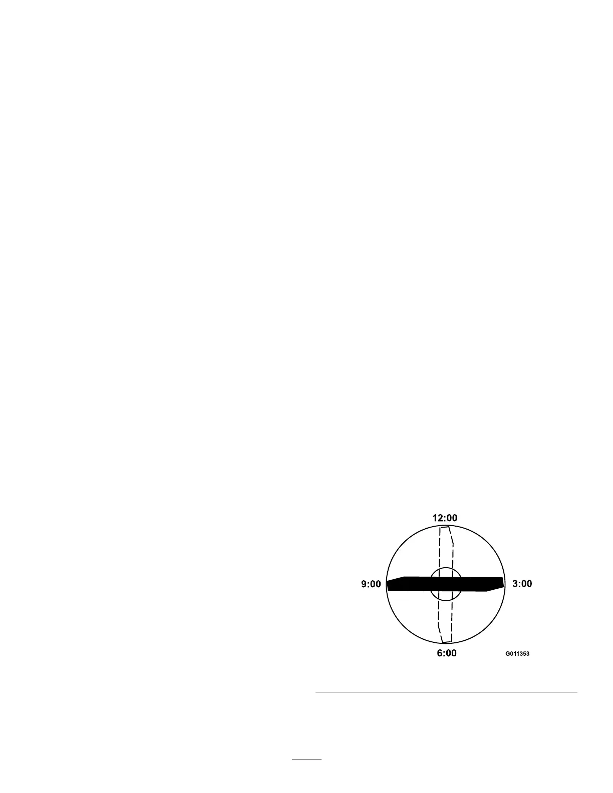
3.Mark1endofthebladewithapaintpenor
marker.Usethisendofthebladetocheckall
heights.
4.Positionthecuttingedgeofthemarkedendof
thebladeat12o’clock(straightaheadinthe
directionofmowing)(Figure127)andmeasure
heightfromtabletocuttingedgeofblade.
g011353
Figure127
5.Rotatethemarkedendofthebladetothe3and
9o’clockpositions(Figure127)andmeasure
theheights.
85
 Loading...