6.Comparethe12o’clockmeasuredheighttothe
height-of-cutsetting.Itshouldbewithin0.7mm
(0.030inch).The3and9o’clockheightsshould
be1.6to6.0mm(0.060to0.240inch)higher
thanthe12o’clocksettingandwithin2.2mm
(0.090inch)ofeachother.
Ifanyofthesemeasurementsarenotwithin
specication,proceedtoAdjustingtheBladePlane
(page86).
AdjustingtheBladePlane
Startwiththefrontadjustment(change1bracketata
time).
1.Removetheheight-of-cutbracket,(front,left,or
right)fromthecutting-unitframe(Figure128).
2.Adjust1.5mm(0.060inch)shimsand/or0.7
mm(0.030inch)shimsbetweenthecutting-unit
frameandbrackettoachievethedesiredheight
setting(Figure128).
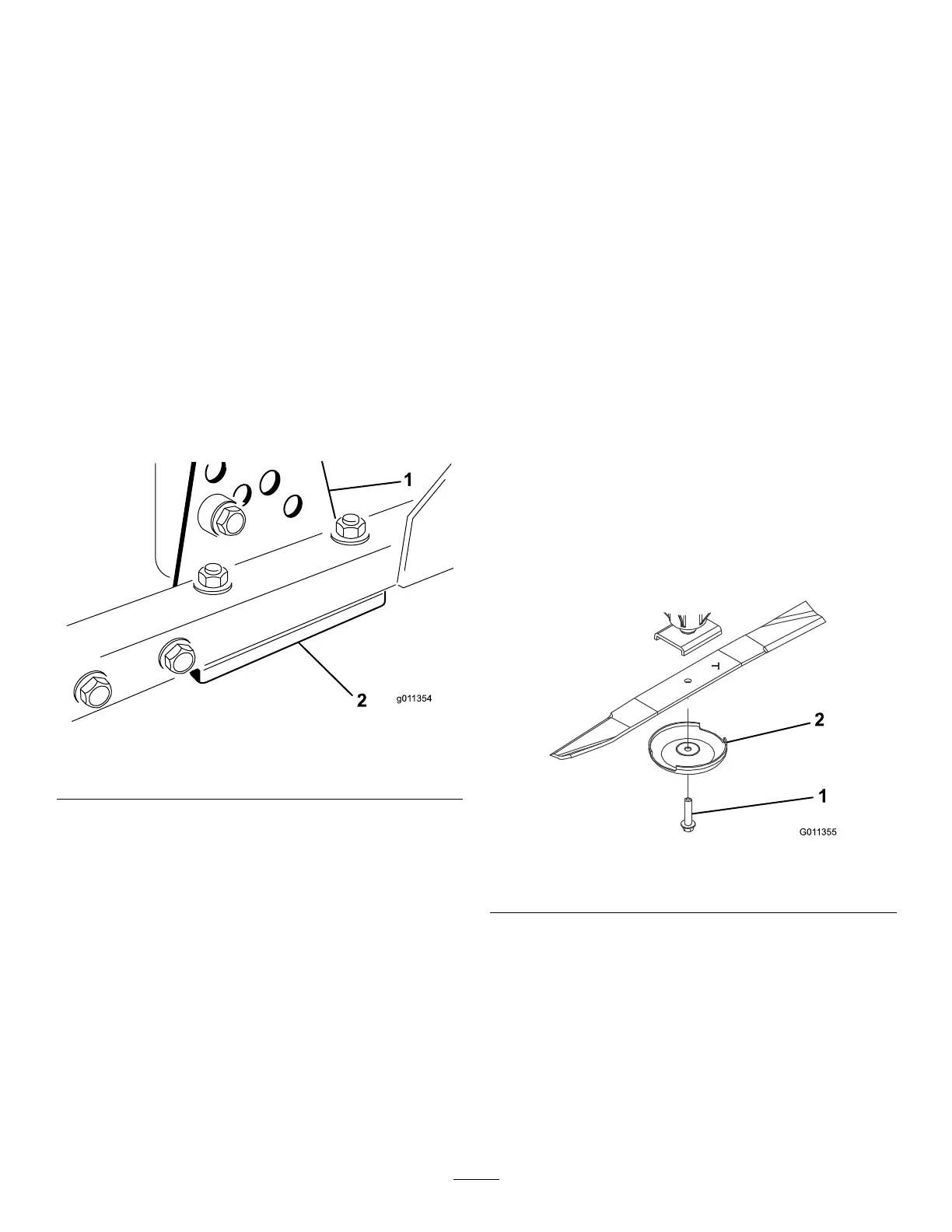
g011354
Figure128
1.Height-of-cutbracket2.Shims
3.Installtheheight-of-cutbrackettothecutting-unit
framewiththeremainingshimsassembled
belowtheheight-of-cutbracket.
4.Securethesocket-headbolt/spacerandange
nut.
Note:Socket-headbolt/spacerareheld
togetherwiththread-lockingadhesivetoprevent
thespacerfromfallinginsidethecutting-unit
frame.
5.Verifythe12o’clockheightandadjustifneeded.
6.Determineifonly1orboth(rightandleft)
height-of-cutbracketsneedtobeadjusted.
Note:Ifthe3or9o’clocksideis1.6to6.0mm
(0.060to0.240inch)higherthanthenewfront
heightthennoadjustmentisneededforthat
side.Adjusttheothersidetowithin±2.2mm
(0.090inch)ofthecorrectside.
7.Adjusttherightand/orleftheight-of-cutbrackets
byrepeatingsteps1through4.
8.Securethecarriageboltsandangenuts.
9.Verifythe12,3,and9o’clockheights.
RemovingandInstalling
theCutting-UnitBlade(s)
Replacethebladeifithitsasolidobject,isout
ofbalance,orisbent.AlwaysusegenuineT oro
replacementbladestoensuresafetyandoptimum
performance.
1.Parkthemachineonalevelsurface,raisethe
cuttingunittothetransportposition,engagethe
parkingbrake,shutofftheengine,andremove
thekey.
Note:Blockorlockthecuttingunittopreventit
fromaccidentallyfalling.
2.Grasptheendofthebladeusingaragor
thickly-paddedglove.
3.Removethebladebolt,anti-scalpcup,and
bladefromthespindleshaft(Figure129).
g011355
Figure129
1.Bladebolt2.Anti-scalpcup
4.Installtheblade,anti-scalpcup,andbladebolt
andtightenthebladeboltto115to149N∙m(85
to110ft-lb).
Important:Thecurvedpartoftheblade
mustbepointingtowardtheinsideofthe
cuttingunittoensurepropercutting.
Note:Afterstrikingaforeignobject,torqueall
spindle-pulleynutsto115to149N∙m(85to110
ft-lb).
86

 Loading...