Assembly
12
DESCRIPTION USEQTY.
Fuel tank
Bolt 5/16–1/ x 7/8” (22.5 mm)
Lock washer 5/16”
W
asher 5/16”
Stud
Spring
Hose clamp
1
2
2
4
2
2
1
Install fuel tank
Operator’
s Manual
Engine Operator
’
s Manual
Parts Catalog
Registration card
1
1
1
1
Read before operating machine
Fill out and return to T
oro
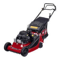
Install
Front Castors
1. Align castors with holes on top and front of
mower and insert (8) 3/8–16 x 3/4” (19 mm)
bolts through mower. Secure with (8) 3/8–16
flange nuts below mower (Fig. 1).
Note: Tighten lower bolts first to pull castor
against front, then top bolts last.
2. Torque bolts to 30–35 ft. lb. (40–47 Nm).
m–3777
Figure 1
1. Front
castor
2. Bolt
3/8–16 x
3/4” (19 mm)
3. Flange
nut 3/8–16
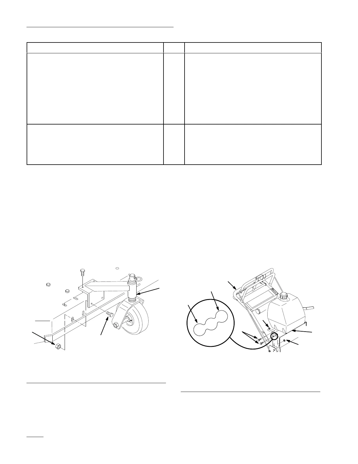
Install
Upper Handle
1. Position handle outside frame and align upper
handle mounting holes with desired mounting
holes in rear frame. High, medium or low
according to operators height (Fig. 2).
2. Secure each side with (2) 3/8–16 x 1” (26mm)
bolts and (2) 3/8–16 locknuts (Fig. 2).
3. Torque bolts to 25 ft. lbs. (34 Nm).
m–4213
Figure 2
1. Upper
handle
2.
Rear frame
3.
Bolt 3/8–16 x 1” (26mm)
4.
Locknut 3/8
5. Low
6. High
 Loading...