g027477
Figure66
3.Repeatfortheoppositelter.
4.Installthelterguardsovereachlterthatyou
previouslyremoved(Figure65).
5.Usethe3screwstosecurethelterguards
(Figure65).
AddingHydraulicFluid
1.Verifythattheventplugsareremovedbefore
addingtheuid.
2.Slowlypourthespecieduidthroughthe
expansionreservoiruntiluidcomesoutof1of
thevent-plugholes;refertoHydraulicSystem
Specications(page43).
3.Installtheventplug(Figure65).
4.Torquetheplugto20N∙m(15ft-lb).
5.Continuetoadduidthroughtheexpansion
reservoiruntiluidcomesoutoftheremaining
vent-plugholeonthesecondtransmission.
6.Installtheoppositeventplug.
7.Torquetheplugto20N∙m(15ft-lb).
8.Pivotthetransaxleguardsupandsecureboth
with2boltsand2nuts(Figure64).
9.Installtheguardplate(Figure63).
10.Continuetoadduidthroughtheexpansion
reservoiruntilitreachestheFULLCOLDlineon
theexpansionreservoir.
11.ProceedtoBleedingtheHydraulicSystem
(page45).
Important:Failuretobleedthehydraulic
systemafterchangingthehydrauliclters
anduidcanresultinirreparabledamageto
thetransaxledrivesystem.
BleedingtheHydraulic
System
1.Parkthemachineonalevelsurface,disengage
thePTO,andengagetheparkingbrake.
2.Shutofftheengine,removethekey,andwait
forallmovingpartstostopbeforeleavingthe
operatingposition.
3.Raisetherearofthemachineontojackstands
highenoughtoraisethedrivewheelsoffthe
ground.
4.Movebothbypassleversrearwardthroughthe
keyholeanddowntolocktheminplace(Figure
67).
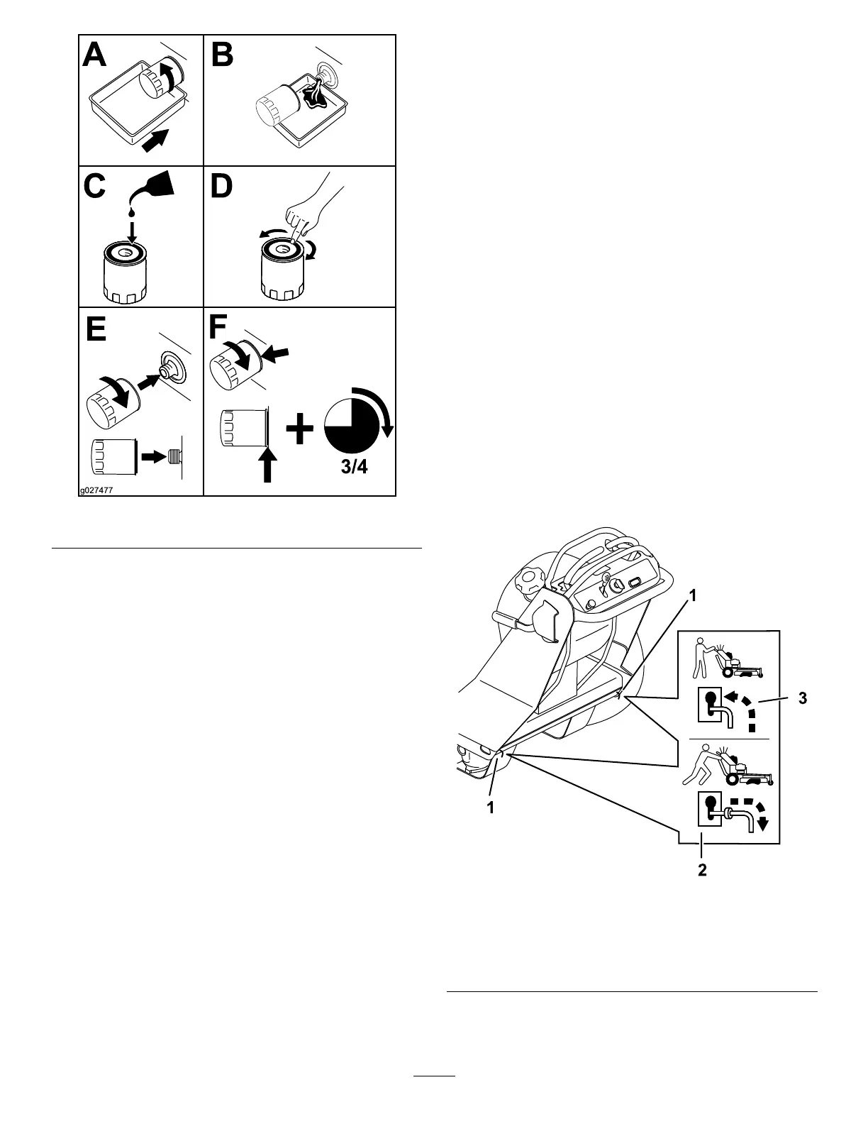
g303749
Figure67
1.Bypass-leverlocations
3.Leverpositionforbleeding
thetransmission
2.Leverpositionfor
operatingthemachine
5.Starttheengine.andmovethethrottlecontrol
tohalfthrottle.
45
 Loading...