CAUTION
Ifyouleavethekeyintheswitch,someonecouldaccidentlystarttheengineandseriously
injureyouorotherbystanders.
Removethekeyfromtheswitchbeforeyouperformanymaintenance.
Note:After50hoursandthenevery100hoursthereafter(150,250,350,etc.),thehourmeterdisplaysCHG
OILtoremindyoutochangetheengineoil.Afterevery100hours,thescreendisplaysSVCtoremindyouto
performtheothermaintenanceproceduresbasedona100-,200-,or400-hourschedule.Thesereminders
comeonstarting3hourspriortotheserviceintervaltimeandashatregularintervalsfor6hours.
Pre-Maintenance
Procedures
MaintenanceSafety
•Parkthemachineonalevelsurface,disengage
theauxiliaryhydraulics,lowertheattachment,
engagetheparkingbrake(ifequipped),shut
offtheengine,andremovethekey.Waitforall
movementtostopandallowthemachinetocool
beforeadjusting,cleaning,storing,orrepairingit.
•Cleanupoilorfuelspills.
•Donotallowuntrainedpersonneltoservicethe
machine.
•Usejackstandstosupportthecomponentswhen
required.
•Carefullyreleasepressurefromcomponentswith
storedenergy.
•Disconnectthebatterybeforemakinganyrepairs;
refertoServicingtheBattery(page32).
•Keepyourhandsandfeetawayfromthemoving
parts.Ifpossible,donotmakeadjustmentswith
theenginerunning.
•Keepallpartsingoodworkingconditionandall
hardwaretightened.Replaceallwornordamaged
decals.
•Donottamperwiththesafetydevices.
•UseonlyToro-approvedattachments.
Attachmentscanchangethestabilityandthe
operatingcharacteristicsofthemachine.Youmay
voidthewarrantyifyouusethemachinewith
unapprovedattachments.
•UseonlygenuineTororeplacementparts.
•Ifanymaintenanceorrepairrequirestheloader
armstobeintheraisedposition,securethearms
intheraisedpositionwiththehydraulic-cylinder
lock(s).
UsingtheCylinderLock
WARNING
Theloaderarmsmaylowerwhenintheraised
position,crushinganyoneunderthem.
Installthecylinderlock(s)beforeperforming
maintenancethatrequiresraisedloaderarms.
InstallingtheCylinderLock
1.Removetheattachment.
2.Raisetheloaderarmstothefullyraisedposition.
3.Shutofftheengineandremovethekey.
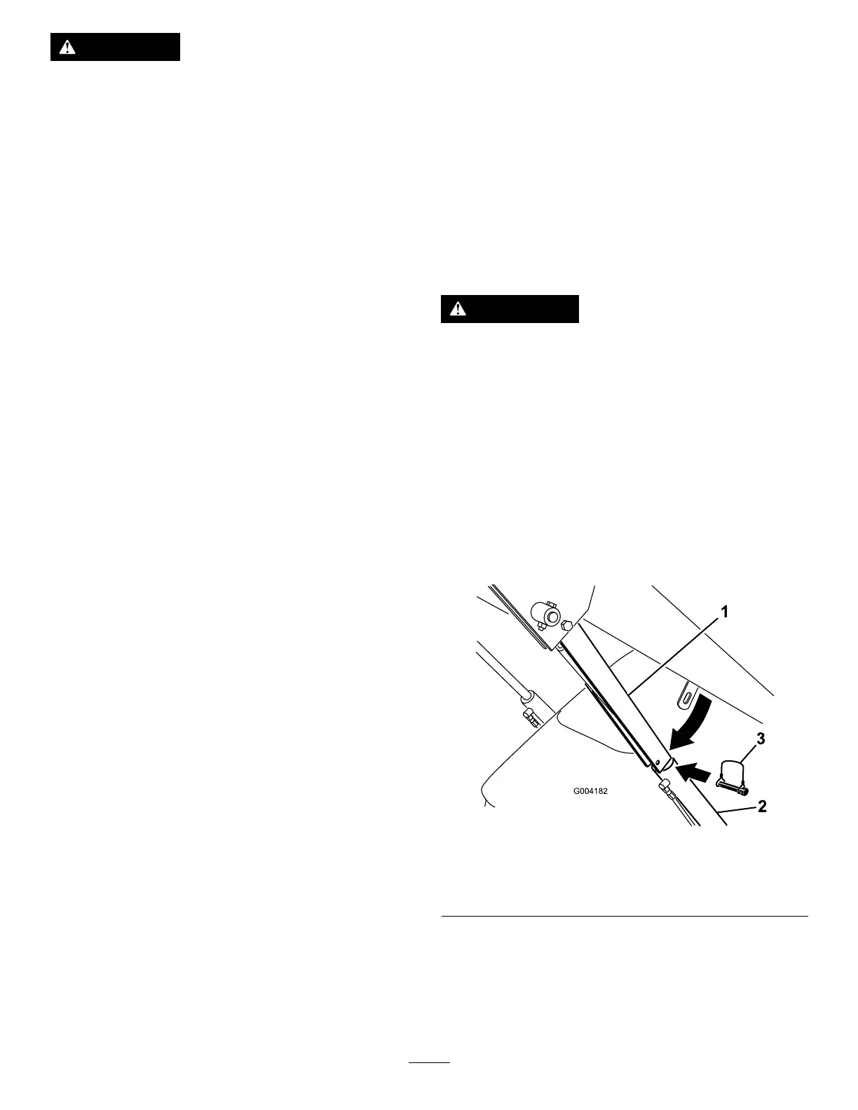
4.Removethelynchpinsecuringthecylinderlock
totheloaderarm(Figure22).
g004182
Figure22
1.Cylinderlock
3.Lynchpin
2.Liftcylinder
5.Lowerthecylinderlockoverthecylinderrodand
secureitwiththelynchpin(Figure22).
6.Slowlylowertheloaderarmsuntilthecylinder
lockcontactsthecylinderbodyandrodend.
22
 Loading...


