Add-On Module Installation
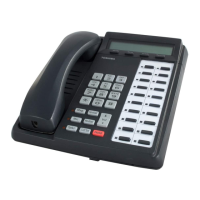
Toshiba DP5000-Series Digital Telephones
15 of 20
Add-On Module Installation
Each add-on module is packaged with the metal brackets and screws used to attach the ADM to a
DP5000-series telephone, or another ADM. The ADM package also includes the short line cord to connect
the telephone to the ADM or the ADM to a second ADM.
The ADM and telephone bases are connected together with metal brackets to form a single unit. The ADM
and telephones tilt independently.
The ADM Installation follows:
1. Unplug the line cord from the telephone.
2. Use the brackets and screws included in the box to attach the ADM base to the telephone base. Refer
to Figure 3.
3. Use the ADM cable included to connect from the telephone ADM connector to the ADM ‘IN” connector.
If a second ADM is attached, that cable runs from the first ADM “OUT” connector to the second ADM
“IN” connector. Refer to Figure 3.
4. Plug in the DP5000-series telephone line cord. If the DDM5060 was attached replace the line cord with
the two-pair line cord included with the DDM5060.
CAUTION! Unplug the line cord from the DP5000-series telephone before attaching the ADM.
Plugging the ADM cable in while the DP5000-series telephone is powered will
damage the telephone, ADM or both.
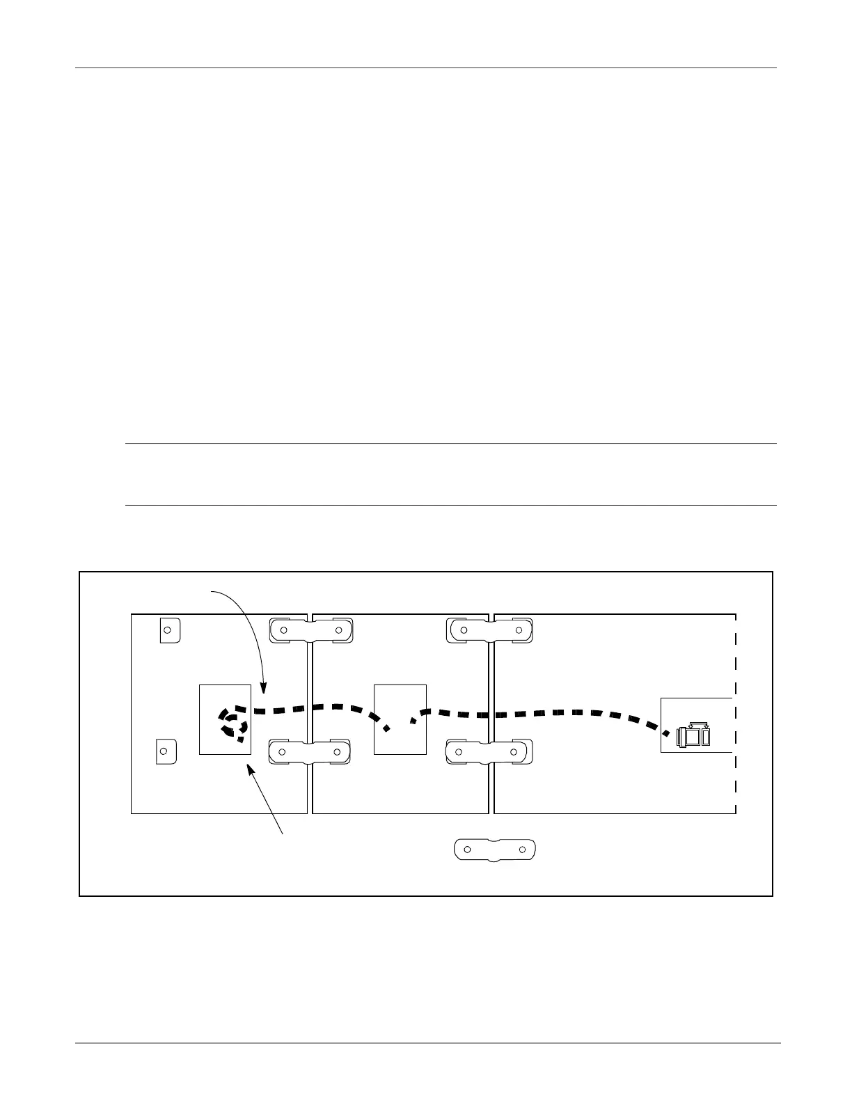
Figure 3 DP5000-Series ADM Connection
DP5000-series TelephoneADMADM
ADM connection bracket
ADM cable
ADM cable is routed under the clips
Remainder of cable length is secured
in the connector recess.
INOUTIN
 Loading...