12 TC-net 100 Installation and Wiring Manual
Chapter 3 TC-net 100 Cabling (Twisted-Pair Cable)
3
Warning
• Before starting connecting the cables, make sure that power has been switched off. Other-
wise, there is the danger of electric shock.
• Never disassemble any part other than specified in the manual. Disassembly of the product
can cause not only failure but also electric shock.
Caution
• A place with as little moisture and dust as possible and not exposed to direct sunlight is rec-
ommended for doing your work.
• Do not expose the product to abrupt temperature changes causing condensation.
• Work gloves are recommended to protect yourself from injuries with angular parts of the
product.
• Static might cause the product to fail. Discharge the static from the human body before start-
ing your work.
• Never touch any other parts than those necessary for performing the work.
• Be careful not to lose the screws and parts removed from the product. Do not drop them
inside the module.
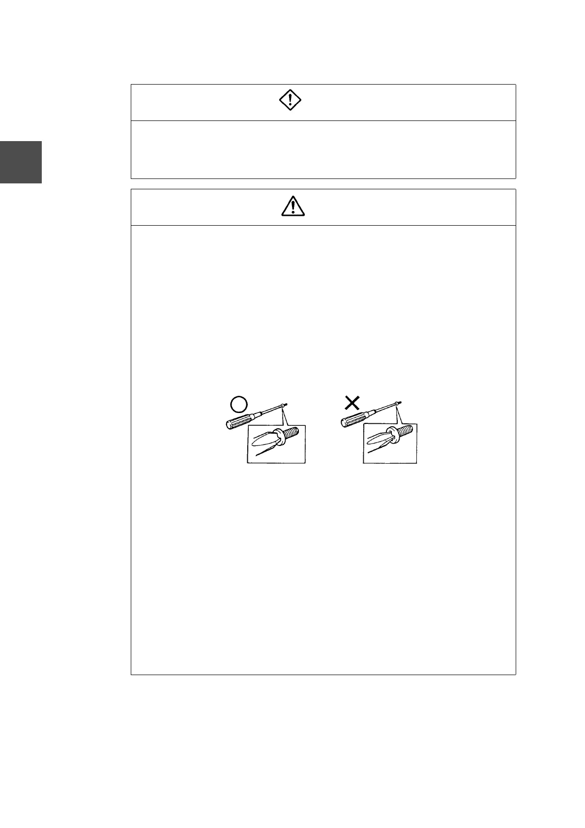
• In using a screwdriver, make sure that it fits the screw to be tightened or loosened. Use of
an unfit screwdriver will not only adversely affect work efficiency but also cause possible
damage to the slots in the screw head.
• Before wiring, check the wiring routes and the spaces for passing the connectors through,
and determine the required cable length. If extra cable length is expected, study ways of
processing it in advance.
• If trunk cabling is needed, either attach a ferrite core to a twisted-pair cable or use a shielded
twisted-pair cable to comply with the EMC Instructions (89/336/EEC). (See figure 3-1.)
• Recommended part: SFC-6 (made by Kitagawa Industries, Ltd.)
• After connecting twisted-pair cables, clamp them securely.
• Be sure to observe the allowable bending radius in installing cables. (See Table 3-1 Allow-
able Cable Bending Radiuses on page 15.)
• In a system of dual TC-net 100 transmission line configuration, correctly wire TN-A and TN-
B. After wiring them, check that they have been correctly connected.
• Have a special grounding pole ready and ground the parts at a single point. Connect the
transmission parts to the grounding terminal of the Integrated Controller. The wrong ground-
ing will cause transmission errors. (Refer to Chapter 4 Installation and Wiring of TC-net 100
Parts and Chapter 6 Grounding.)
• If errors or defects have developed, contact your nearest TOSHIBA service office.
 Loading...