6F8C0942 15
3.1 Twisted-Pair Cabling
3
Cable Installation
Do not bend cables to less than the minimum bending radius. The allowable cable
bending radiuses are shown in Table 3-1 Allowable Cable Bending Radiuses on page 15.
After cable installation, clamp the cables so that the connectors will be free of the cable
load.
Use of Relay Connector Unit
Use a relay connector unit to connect a drop cable (UTP cable) to a trunk cable (STP
cable). Exercise care, when installing the relay connector unit, not to let the connectors
contact each other because they are insulated from the mounting parts.
The cable shield requires Class D grounding at one point. (Refer to Chapter 6
Grounding.)
TC-net 100 Trunk Cable Installation
Use trunk (STP) cables for wiring outside the cabinet. For details, refer to Chapter 5
External Wiring (Twisted-Pair Cable).
Grounding
Have a special grounding pole exclusive to the transmission line ready and ground them
at a single point. Connect the transmission parts to the grounding terminal of the
Integrated Controller.
In cases where other grounding is also present, or where the effect of noise, etc. is
anticipated, have the class D grounding exclusive to transmission
parts ready and use it for one-point grounding. (Refer to Chapter 6 Grounding.)
• If trunk cables are used, attach a ferrite core to the drop cables to comply with the
EMC Instructions (89/336/EEC). (figure 3-1).
Recommended part: SFC-6 (made by Kitagawa Industries, Ltd.)
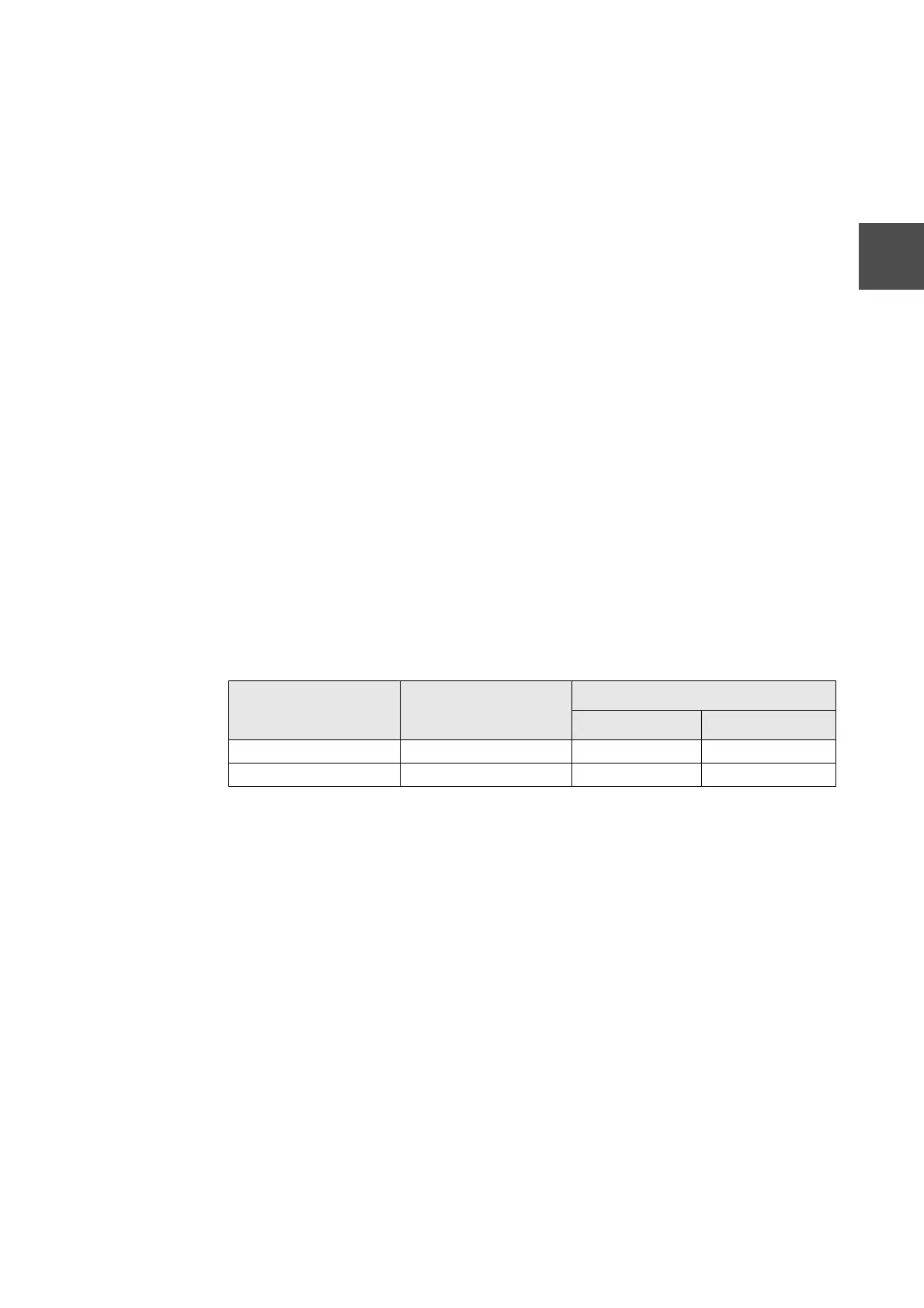
Table 3-1 Allowable Cable Bending Radiuses
Cable Cable Specifications
Allowable Bending Radius (mm)
Clamped Installed
UTP cable
STP cable
 Loading...