INTERFACE MANUAL
4.6 Jumper of Safety Measure Signal
Of the system input signal cables, the following signals are used for the safety
measures.
System input signal cables ····· CN5–16 (STOP)
CN6–34 (SVOFF)
CN5–17 (BREAK)
CN6–16, 35 (EMS2B ~ EMS2C)
CN6–17, 36 (EMS1B ~ EMS1C)
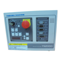
For the connectors provided with the TS2000/TS2100 robot controller, these signals
are already jumpered. If these signals are used or changed, perform wiring with the
jumper of connector removed. When operating the robot without using system
input signals, be sure to connect the attached connectors to the CN5, CN6
connectors on the controller side.
Unless the following signals are used as the system signals, jumper the cables also.
CN5–36 (LOW_SPD)
CN5–35 (CYCLE)
Jumper of connectors
CN5 CN6
16–18 17–18 18–34 —
(35–37) (36–19) 16–35 17–36
!
CAUTION
1. Unless the signals of SVOFF and emergency stop contacts 1 and 2 are
jumpered, the controller servo power cannot be turned on.
2. Unless the CYCLE signal is jumpered, the controller enters the cycle operation
mode.
3. Unless the LOW_SPD signal is jumpered, the low speed is selected for the
robot speed during automatic operation.
4. Unless the signals of STOP and BREAK are jumpered, automatic operation of
the robot is not possible.
STE 71367
– 61 –
 Loading...

