INTERFACE MANUAL
4.9 Fabricating External I/O Signal Cable
When fabricating an external I/O signal cable, observe the following matters.
a. Connectors CN5 and CN6 for the TS2000/TS2100 robot controller should be
either the connectors attached to the controller or equivalent connectors.
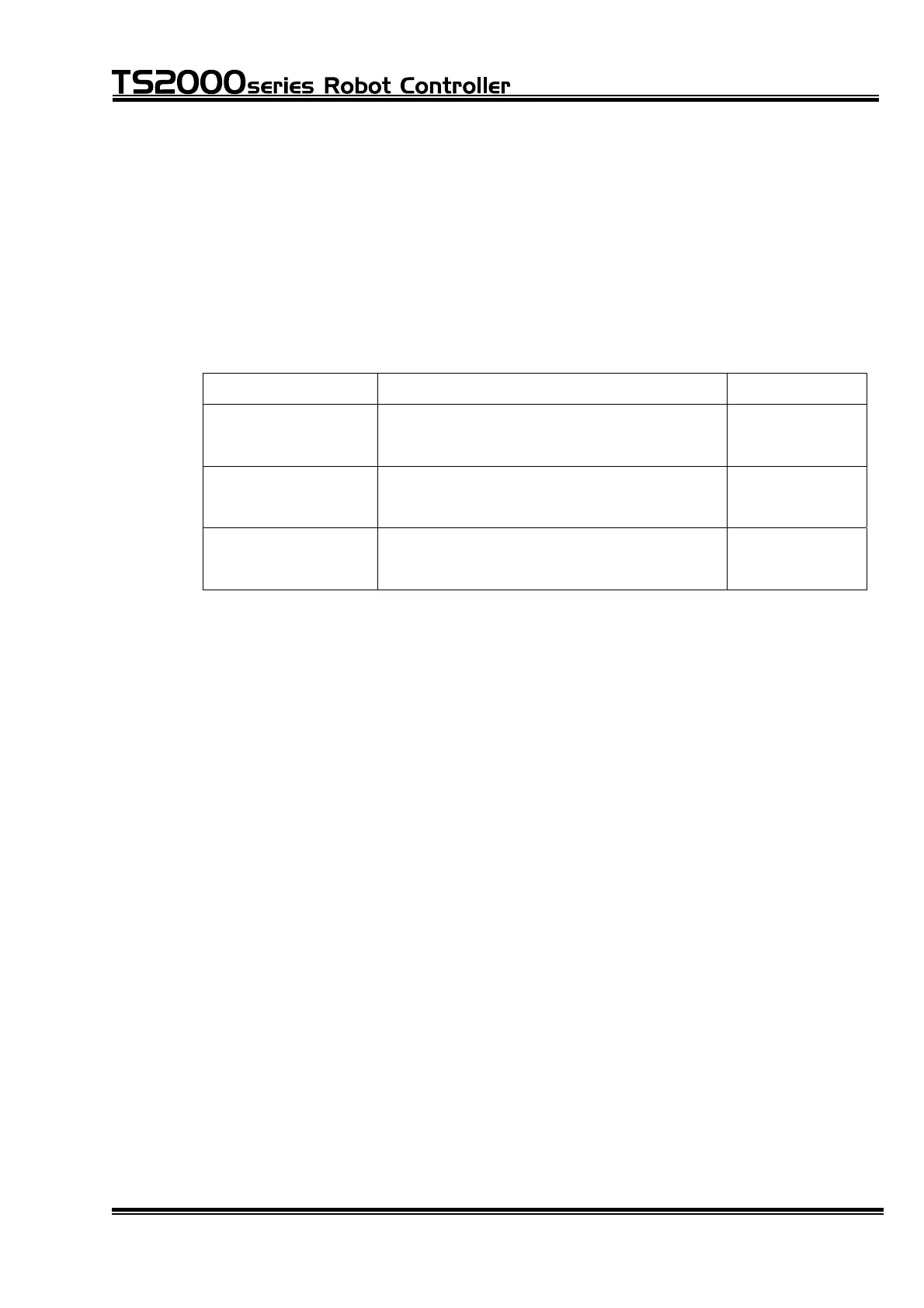
For CN12, prepare the following connector.
The equivalent of other makers (D-SUB connectors) can also be used.
Connector name Type of connector Maker
CN5 XM2D–3701 (socket type connector)
XM2S–3711 (connector cover)
OMRON
CN6 XM2A–3701 (pin type connector)
XM2S–3711 (connector cover)
OMRON
CN12 XM2A–2501 (pin type connector)
XM2S–2511 (connector cover)
OMRON
b. Select the cables which meet the following specifications.
• Core wires : 0.18 mm
2
~ 0.32 mm
2
twisted wires
• Cable outer diameter : Max. 10.5 mm (CN5, CN6), 9 mm (CN12)
• Shield : Batch shield
• Cable length : 30 m or less
NEVER use cables which do not conform to the specifications. Otherwise,
short-circuit or cable melting due to overheated cable core may be caused.
Additionally, the robot may work improperly due to noise.
c. The CN5, CN6 and CN12 connectors are of a solder cup type which joints
cables by soldering. For how to joint cables to connectors and how to shield
cables, see Section 12.
STE 71367
– 81 –

 Loading...


