E6581692
- 7 -
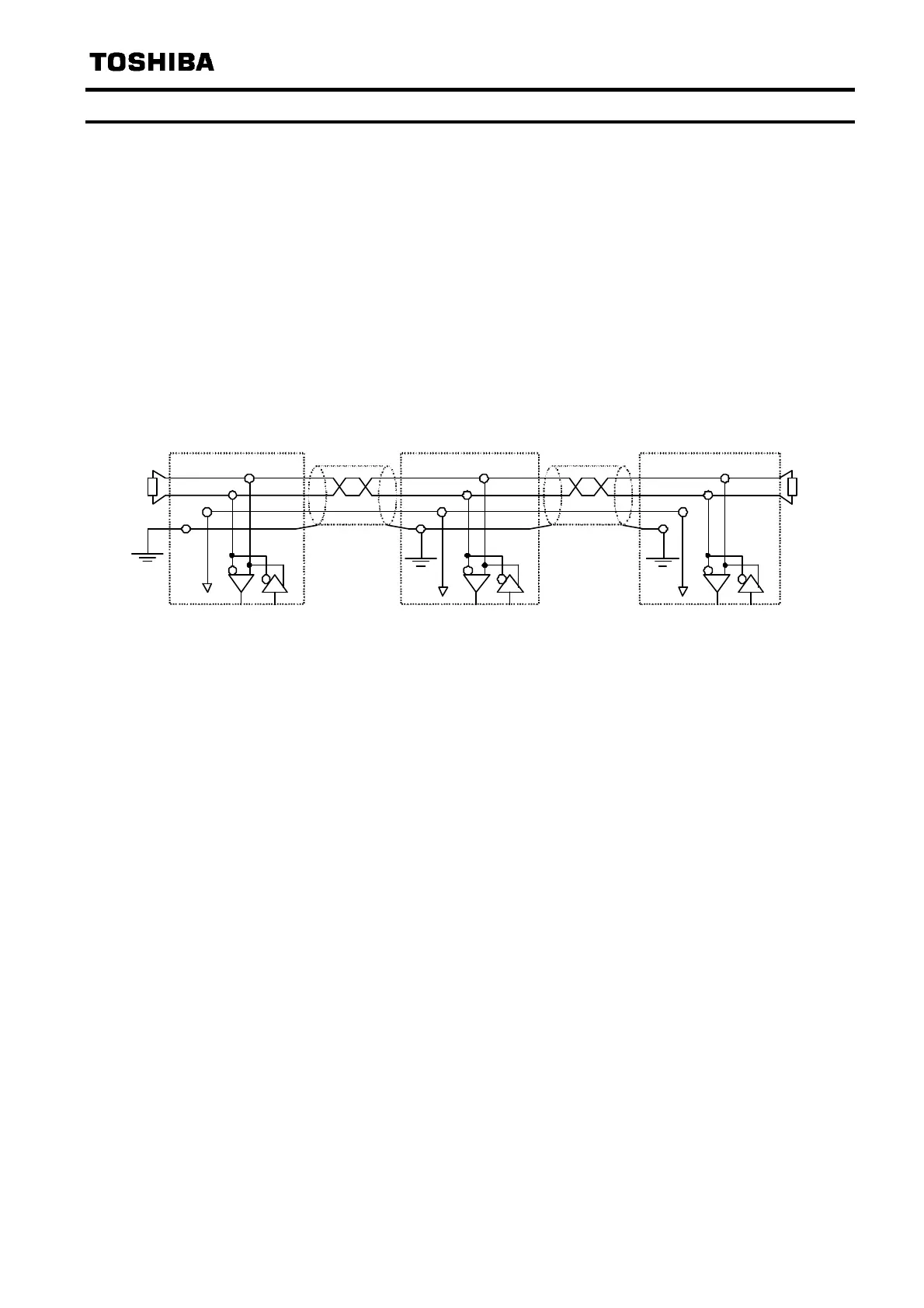
2.7. Network configuration
Make up the network as follows.
- Transmission/reception signals (CAN_H, CAN_L)
Make up the communication path by connecting twisted cables with shield.
- Signal common (CAN_GND)
GND is the signal common.
- Grounding the shield of cable (CAN_SHLD)
Connect the all shield lines of network cable. The shield shall be grounded at one end only prevent
currents from being created.
- Termination resistor
A termination resistance of 120 ohms plus or minus 5% shall be connected at each of the two ends of
the segment medium.
TERM
CAN_H
CAN_L
CAN_GND
Master
120
CAN_H
CAN_L
CAN_GND
Slave Node
CAN_H
CA N_L
CAN_GND
Slave Node
TERM
120
CAN_SHLD
Communication
Cable
Communication
Cable
CAN_SH LD
CAN_SHLD
N.B.:RJ45 connector shield case is connected to the drive frame grounded in the drive.
Keep the network cables 20cm or more separate from the power cables to prevent from
malfunctioning due to electromagnetic noise.
 Loading...