INTERFACE MANUAL
1.6.4 Serial I/O Signal "POD"
Fig. 1.1/Fig.1.2–[15]
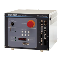
Of the serial input and output signals of four (4) channels equipped on the
TS2000/TS2100 robot controller, the D-SUB 9-pin connector located on the fourth
line from the top of the front connector unit in Fig. 1.1 is POD.
POD is exclusively used for the RS232C and allows communication with the touch
panel controller where an RS232C interface can be connected. Connector "POD"
is used.
1.7 Teach Pendant Cable "TP"
Fig. 1.1/Fig.1.2–[16] (with dummy connector)
This is an interface connecting the TS2000/TS2100 robot controller and teach
pendant (TP1000). The TP1000 is an option. By connecting the TP cable,
creation of motion programs, manual robot guidance, etc., are possible through the
teach pendant. Connector "TP" is used. The TP cable is secured to the teach
pendant and cannot be disconnected from the teach pendant. The standard cable
length is 5 m.
1.8 Remote I/O Cable "EXT–I/O"
Fig. 1.1/Fig.1.2–[9]
This is an RS485 communication terminal connecting the optional remote I/O
module function (TR48DIOCN/TR48DIOC module, etc.) of the TS2000/TS2100 robot
controller. To connect, the terminal block on the rear side of the controller is used.
STE 71367
– 16 –
 Loading...