38
AC-SVX003A-EN
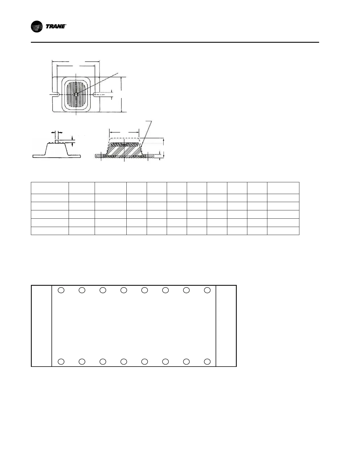
Figure 14. Elastomeric isolator
0.50 in
1.60±0.25
Mounting molded in neoprene
3.0
2.75
0.38
1/2 - 13NC - 2B
0.56 in
F
E
G
D
A
B
C
Table 17. Elastomeric isolator specifications
Max Deflection A B C D E F G
Charcoal 60 1100 0.5 2.5 2.88 0.25 1.13 5.50 4.12 3.38 RDP3-WR
Brown 61 1500 0.5 3.0 2.75 0.38 1.60 6.25 5.00 4.63 RDP4-WR
Brick Red 62 2250 0.5 3.0 2.75 0.38 1.60 6.25 5.00 4.63 RDP4-WR
Lime 63 3000 0.5 3.0 2.75 0.38 1.60 6.25 5.00 4.63 RDP4-WR
Charcoal 64 4000 0.5 3.0 2.75 0.38 1.60 6.25 5.00 4.63 RDP4-WR
Note: Maximum deflection is 0.5 for all isolators.
Mounting Locations, Weights, Isolators
See figure below for mounting point location designations.
Figure 15. Mounting point locations (top view)
2 4 6 8 10 12 14 16
1 3 5 7 9 11 13 15
Main Control Panel
(With user interface TD7)
Control Panel
(Not present on all congurations)
Note: Quantity of isolators varies with unit. See submittal for actual number required for specific unit.
Installation Mechanical
 Loading...


