76
AC-SVX003A-EN
Controls
Overview
Ascend™ chillers utilize the following control/interface
components:
• Symbio™ 800 Controller
• Tracer® AdaptiView™ TD7 Operator Interface
Symbio™ 800
The Symbio 800 controller is a factory-installed, application
specific and programmable controller designed to control
chillers and large packaged HVAC equipment. A 7 inch
user interface features a touch-sensitive color screen that
provides facility managers at-a-glance operating status,
performance monitoring, scheduling changes, and
operating adjustments. Other advanced features include
automated controller back-up, and optional features such
as secure remote connectivity, wireless building
communications, mobile device connectivity, and custom
programming with an expandable I/O.
For more information, see Symbio™ 800 Controller
Installation, Operation, and Maintenance (BAS-SVX080*-
EN).
AdaptiView™ Display
Information is tailored to operators, service technicians,
and owners. When operating a chiller, specific information
is needed on a day-to-day basis—setpoints, limits,
diagnostic information, and reports. This information is
provided through the AdaptiView™ display. Logically
organized groups of information— chiller modes of
operation, active diagnostics, settings and reports put
information conveniently at your fingertips.
For more information, see AdaptiView™ Display with
Symbio™ Controls Ascend™ Air-Cooled Chiller Model
ACR Series C User Guide (AC-SVU003*-EN).
Noise Reduction Mode
When InvisiSound™ Standard with Noise Reduction,
InvisiSound Superior with Noise Reduction or InvisiSound
Ultimate option is selected, noise reduction mode can be
enabled to adjust fan speed and lower maximum sound
levels. Maximum fan speed is configurable form 600 to
1000 rpm (950 rpm factory default). When noise reduction
is enaabled, an additional fan speed clamp setpoint from
70 to 100 percent of maximum fan speed (80 percent
factory default) is available. The noise reduction feature is
accessible through the operator display, external input, or
building automation system. When accessing at Tracer®
AdaptiView™ display, access is found on the Settings
screen.
• Set the Front Panel Noise Reduction Request to ON.
• Adjust the Noise Reduction Condenser Fan Speed
Clamp to desired value.
Tracer TU
The AdaptiView TD7 operator interface allows for daily
operational tasks and setpoint changes. However, to
adequately service chillers, Tracer
®
TU service tool is
required. (Non-Trane personnel, contact your local Trane
office for software purchase information.) Tracer TU adds a
level of sophistication that improves service technician
effectiveness and minimizes chiller downtime. This
portable PC-based service-tool software supports service
and maintenance tasks, and is required for software
upgrades, configuration changes and major service tasks.
Tracer TU serves as a common interface to all Trane
chillers, and will customize itself based on the properties of
the chiller with which it is communicating. Thus, the service
technician learns only one service interface.
The panel bus is easy to troubleshoot using LED sensor
verification. Only the defective device is replaced. Tracer
TU can communicate with individual devices or groups of
devices.
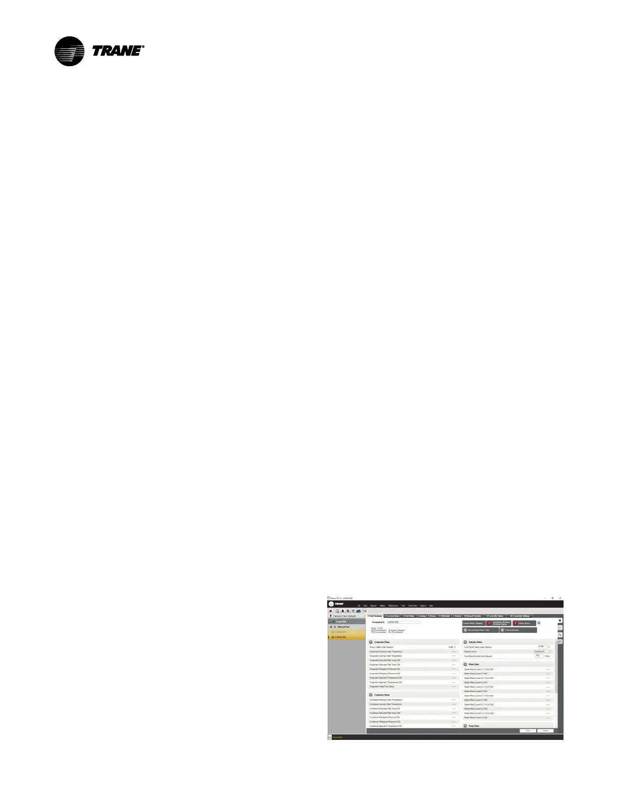
All chiller status, machine configuration settings,
customizable limits, and up to 100 active or historic
diagnostics are displayed through the service-tool software
interface.
LEDs and their respective Tracer TU indicators visually
confirm the availability of each connected sensor, relay,
and actuator.
Tracer TU is designed to run on a customer’s laptop,
connected to the Symbio™ 800 control panel with a USB
cable. See Tracer® TU Service Tool User Guide (BAS-
SVU046*-EN) for laptop requirements.
Notes:
• Tracer TU is designed and validated for this
minimum laptop configuration. Any variation
from this configuration may have different
results. Therefore, support for Tracer TU is
limited to only those laptops with the
configuration previously specified.
• For more information, see Tracer ®TU Service
Tool User Guide (BAS-SVU046*-EN).
Figure 27. Tracer TU
 Loading...


