ACC-SVN28A-EN 13
Installation
Zone Sensor Status
Indicators
The Unit Control Processor has the
capability of communicating four
input signals (HEAT, COOL, ON,
SERVICE) to the respective Zone
Sensor Module (ZSM) icons when
appropriately wired.
Each of these Zone Sensor icons will
respond to the Controller in 1 of 3
conditions;
OFF – No icon will be displayed when
the unit is not operating.
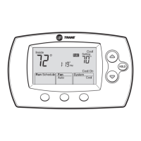
Figure 9. Override run state
Table 8. Override run state settings
Key Press Action
Hold Temp Enter Temporary Override
Menu
Mode Advances one position for
MODE selection
Fan (CV/HP
only)
Toggles Fan Operation Setting
if Option 10 is set to 1
UP Arrow Enter Temporary Override
Menu
DOWN
Arrow
Enter Temporary Override
Menu
Erase Cancels Override
Programming and returns to
Normal Run State
Time+ and -
simultaneou
sly for 4
seconds
Toggles Keypad Lockout if
Option 14 is set to 1
TIME
PROGRAM
DAY
ERASE
HOLD TEMP
MODE
FAN
AUTO
FAN
MODE
COOL
OCCUPIED
Override Run State Screen
Blinking
indicates
Program in
Override
76
9:45
OVERRIDE
ROOM TEMP
AM
Mo
ON – Indicates that the unit is
operating in the Mode reflected by
the illuminated icon.
FLASHING – Indicates that the
system is not operating properly and
some type of service may be
required.
The Controller Status Input
conditions and the respective zone
sensor terminals are;
• Terminal # 7 – (HEAT Icon)
– ON – Indicates by a
continuously illuminated icon
that the unit is operating in
the Heating Mode.
– FLASHING – The HEAT
FAILURE icon indicates that a
system failure in the Heating
Mode has occurred.
• Terminal # 8 – (COOL Icon)
– ON – Indicates by a
continuously illuminated icon
that the unit is operating in
the Cooling Mode.
– FLASHING – The COOL
FAILURE icon indicates that a
system failure in the Cooling
Mode has occurred.
• Terminal # 9 – (ON Icon)
– OFF – The Colon (:) displayed
in the Clock is not flashing,
the System is OFF.
– ON – The Colon (:) displayed
in the Clock is flashing, the
System is ON.
– FLASHING – The TEST icon
indicates the System is
operating in the Test Mode.
• Terminal # 10 – (SERVICE Icon)
– ON - Indicates by a
continuously illuminated icon
that the unit requires service.
– FLASHING – Indicates that a
Fan Failure has occurred and
service is required.
Note: Voyager 27.5 - 50 Ton - For
Combination Diagnostics (ie.
Cool Fail plus Heat Fail) See
Unit IOM or Diagnostics
Label on the unit control box
door.
If number 2 is selected for option 16
in the Options Menu, any of the
FLASHING signals will sound an
audible buzzer. To reset the buzzer,
press the ERASE Key.
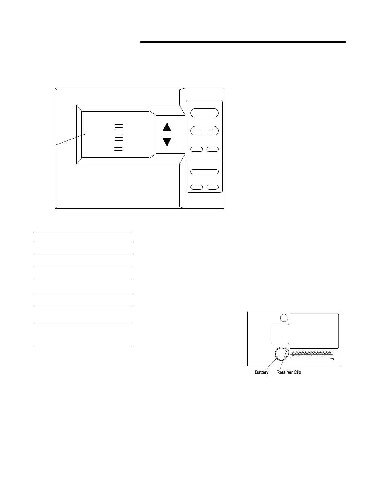
Battery Replacement
To replace the battery, depress the
metal retainer clip and the battery
will spring forward. Refer to the
illustration for battery and clip
location.
Replace the battery with CR2032
Lithium 3V or equivalent.
Figure 10. Battery placement
 Loading...