6 ACC-SVN28A-EN
Installation
the UCM (HEAT, COOL, SYSTEM
“ON”, SERVICE). Four (4) wires from
the UCM should be connected to the
appropriate terminals (7, 8, 9 & 10) on
the ZSM.
Auxiliary Relay (3 Wires
Optional)
The auxiliary relay located on the
ZSM is energized during OCCUPIED
periods. The auxiliary relay is form C,
rated for 1.25 Amps at 30 VAC. Figure
3 illustrates the terminal
configuration.
Note: Guidelines for wire sizes and
lengths are shown in Table 1.
The total resistance of these
low voltage wires must not
exceed 2.5 ohms per
conductor. Any resistance
greater than 2.5 ohms may
cause the control to
malfunction due to excessive
voltage drop.
Note: Do not run low-voltage
control wiring in same
conduit with high-voltage
power wiring.
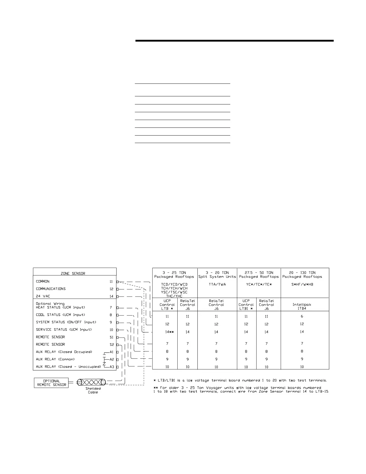
Figure 4. Zone Sensor Connection Diagram
Wiring The Sub Base
Connecting the wires
1. Strip approximately ¼ inch of
insulation from each wire and
connect the wiring to the
appropriate terminals at the unit
control panel.
2. Remove the Terminal Block from
the hardware package and
connect the wiring to the
appropriate terminals at the
Table 1. Zone Sensor Maximum
Lengths and Wire Size
Distance from Unit
to Control
Recommended
Wire Size
Feet Meters Gauge Area
0 - 150 0 - 46 22 0.33 mm2
151 - 240 47 - 73 20 0.50 mm2
241 - 385 74 - 117 18 0.75 mm2
386 - 610 118 - 185 16 1.30 mm2
611 - 970 186 - 296 14 2.00 mm2
Zone Sensor sub base. In
general, zone sensor
connections use the convention
of connecting Zone Sensor
terminals to like numbered Unit
terminals (1 to 1, 2 to 2, etc.).
Refer to Figure 3.
3. Firmly tighten each screw
terminal.
4. Attach the terminal block to the
Sensor PC Board.
5. Fit the wires as close to the sub
base as possible. Be sure to
push the excess wire into the
wall and plug the hole with
nonflammable insulation to
prevent drafts from affecting the
sensor.
Note: Do Not Coil Excess Wire
Inside Sub Base! Push All
Excess Wire Inside Handy
Box Or Inside Wall Cavity.
 Loading...