Drive and Cabinet
AFDK-SVU01C-EN 13
Drive Cabinet Component
Locations
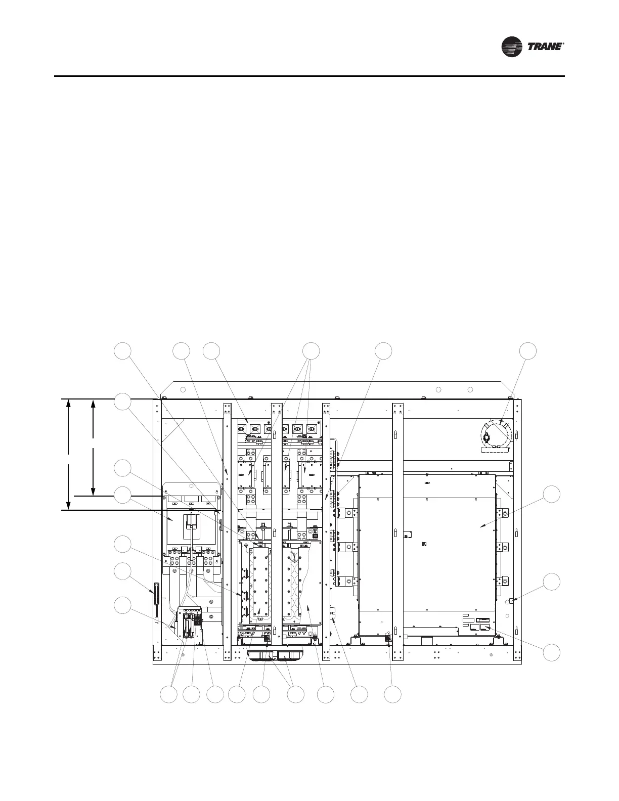
Frame 4 Units (900, 1200 A)
The main drive components for a Frame 4 unit are listed
below. Each numbered item corresponds to a number in
Figure 4.
1. Circuit Breaker, 600 V
2. Circuit Breaker Operating Mechanism
3. Inductor
4. AC Contactor
5. Power Module Assembly (refer to Figure 5, p. 15 and
Figure 6, p. 16 for details)
6. Input Filter Capacitor Assembly
7. Input Filter Capacitor Guard Panel
8. Fans, 115 Vac, Inductor (4)
9. Transformer, 3 kVA
10. Fan, 115 Vac, Contactor
11. Resistors, 100k Ohms, 50 W
12. Pre-charge Resistors
13. Relay, Pump, and Control Power Terminals
14. Fuse, Class RK-5, 600 V, 10 A (2)
15. Fuse, Class CC, 600 V, 25 A (1)
16. Fuse, Class CC, 600 V, 10 A (1)
17. Fuse, Class T, 600 V, 300 A (3)
18. Fuse, Class CC, 600 V, 20 A (3)
19. Fuse, Class CC, 600 V, 1 A (3)
20. Ground Lug, 2–600 MCM
21. Nameplate, Power Module
22. Door Inter-lock (2)
23. Magnetic Choke
Figure 4. Drive component loca
tions: Frame 4 units
(a)
9
2
11
614 1615 22 8
7
1
17
3
L1 L3L2
12 4
19 22
L3
L2
W
V
13
L1
U
18
5
10
20
21
23
Grounding
Connection
Input Power
Wiring Connection
29.52 in.
23.45 in.
(a)Material courtesy of Rockwell.

 Loading...