EasyManuals Logo
Home>Trane>Chiller>CVHG

Trane CVHG Installation Instructions

Trane CVHG
48 pages
To Next Page IconTo Next Page
To Previous Page IconTo Previous Page
Page #16 background imageLoading...
Page #16 background image
16 AFDH-SVN03H-EN
AFDH Drive Package Specifications
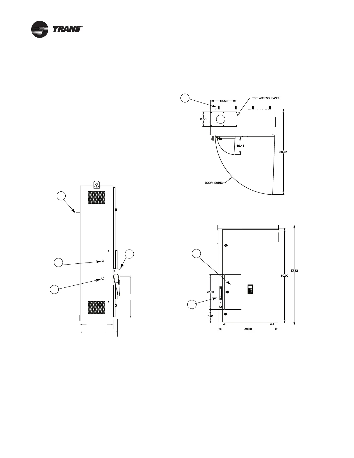
D-Frame Drive Unit Mount Dimensions
Figure 6. Top, front, and side view of D-Frame AFDH cabinet with dimensions
1. UCP2™ or CH531 / Tracer® AdaptiView™ control box
2. Z-bracket mounting studs (each stud = 3/8-16 x 1.75 in.)
3. Two-piece access door cover on top of the 7 in. x 14 in. incoming power wire cutout
4. Electrical disconnect switch
5. 0.88 in. diameter cutout for 0.50 in. electrical conduit
6. 1.13 in. diameter cutout for 0.75 in. electrical conduit
15.81"
17.13"
18.90
1
2
2
3
4
4
5
6

Table of Contents

Other manuals for Trane CVHG

Questions and Answers:

Question and Answer IconNeed help?

Do you have a question about the Trane CVHG and is the answer not in the manual?

Trane CVHG Specifications

General IconGeneral
BrandTrane
ModelCVHG
CategoryChiller
LanguageEnglish

Related product manuals