AFDH Drive Package Specifications
20 AFDH-SVN03H-EN
D-Frame Drive Unit Components
Drive Unit Component Parts Housed within the Custom Enclosure
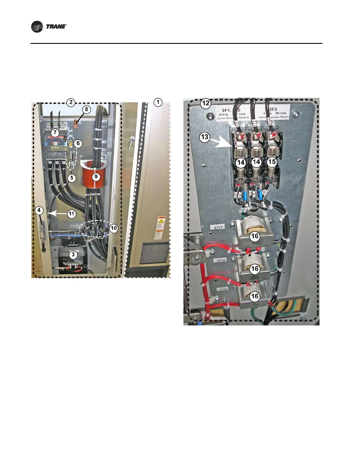
Figure 9. Mounting location of D and E-Frame custom
enclosure parts
1. Right-hand cabinet section houses the TR200 drive module for the
unit. For the part numbers of the components housed within the
left-hand custom enclosure section of the unit by drive model size,
refer to the following tables.
2. Custom enclosure section of unit
3. Transformer (4 KVA)
4. Circuit breaker handle
5. Circuit breaker cable
6. Circuit breaker mechanism
7. Circuit breaker
8. Ground lug
9. Choke
10. Current transformers (CTs)
11. To view the components attached to the left interior wall of the
enclosure, go to the next page in the manual.
Figure 9. (continued) Mounting location of D-Frame
custom enclosure parts
12. Custom enclosure components mounted on left interior wall of
cabinet. For the component part numbers by drive model size,
refer to the following tables.
13. Fuse holder; 3 Pole (for fuses 2F1, 2F2, and 2F3)
14. Left hand fuse = 2F1 and middle fuse = 2F2. Both fuses have
identical voltage and amperage ratings.
15. Fuse 2F3
16. Potential Transformers (PTs). From top to bottom: PT 2T17, 2T18,
and 2T19. All three PTs have identical ratings.
 Loading...


