35
Section 16. Filters
16.1 Filter Considerations
Filter in
air handler
cabinet
(Upflow
Application)
A filter must be installed within the system. •
A filter channel is provided in the unit, at the bot- •
tom of the Blower/Filter compartment.
For customer ease of fil ter maintenance, it is •
recommended that a properly sized remote filter
grill(s) be installed for units that are difficult to
access. Airflow should not exceed the maximum
rated velocity of the filter being used.
Cabinet Size* A B C
Filter Size 16 x 20 20 x 20 22 x 20
* Cabinet size is indicated by the 7th digit in model number.
Table 16.1 Filter Sizes
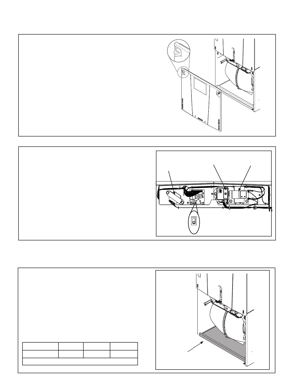
15.1 Remove the blower door panel.
Section 15. Time Delay Switch Adjustment
Set the fan off delay setting using the Fan Delay
Relay Switch (TDR) located on the blower control
mounting plate located on the front of the blower.
Factory default delay is 90 seconds.
Choke Coil
3/4 &1 HP
motors only
Door Switch
Transformer
Fan Delay
Relay Switch
15.2 Time Delay Relay (TDR) Switch
The Blower/Filter panel is removed using 1/4 turn
thumb screws.
1. Turn thumb screws on Blower/Filter panel.
2. Pull top of panel out, away from cabinet.
3. Lift panel up out of channel.
4. Set aside.

 Loading...
