14 RLC-SVD05A-EN
The CH530 power supply has no communication capabilities. It provides 24VDC
to the LLIDs and acts as the trunk for the IPC bus. It is also used as a “central
hub” to provide a starting point for up to 5 IPC bus cables.
Troubleshooting
The input voltage on the power supply is 23 to 30 VAC and the output voltage is
22.8 to 25.2 VDC.
The input voltage should fall within the following values.
Ta ble 2 list the values for the output voltage on the power supply. If the green
LED 1 is lit it implies that there is a good DC output voltage being produced by
the board. Output for terminals J1, J3, J4, J5 and J11 are the same. The voltage
output should be within ± 5%.
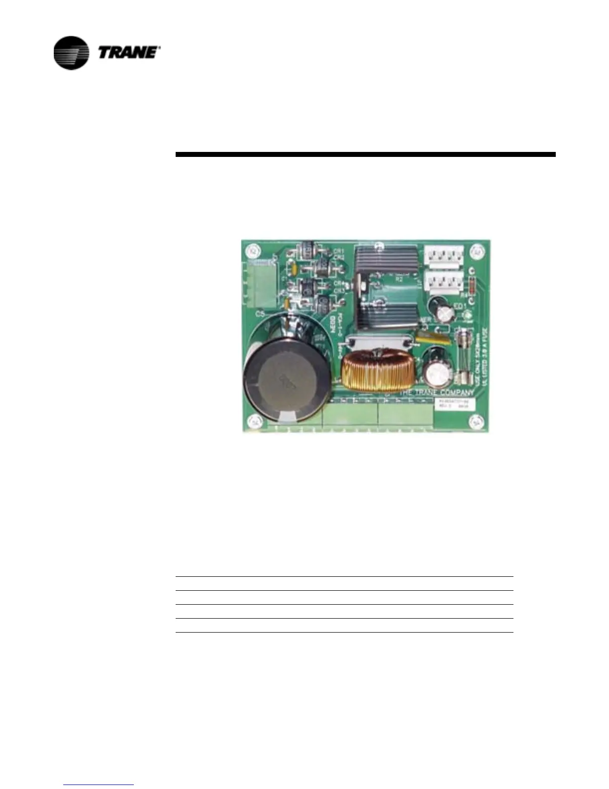
Power Supply
Figure 8. Power Supply
Table 1. Input Voltage
Terminations Voltage Min. Max
J2-1 27 VAC 23 VAC 30 VAC
J2-2 27 VAC 23 VAC 30 VAC
J2-3 GRD
 Loading...


