48 RLC-SVD05A-EN
The CHHP (GPII) compressor is a “screw” or helical rotor design with two rotors,
one directly driven by the motor called the male and the other driven by the
lobes of the male called the female.
CHHP compressors have a female step load solenoid valve and male load/unload
solenoid valves that are utilized for capacity control. The female step load
solenoid is so named because it acts on the female rotor side of the compressor,
and its function is to “pilot” a larger valve inside the compressor that opens to
bypass compressed vapor back to the suction of the compressor. This bypass
action causes a “step” difference in the capacity of the compressor.
On the Male rotor side of the compressor is the male port unloader piston, which
can move laterally along the male rotor. Small bypass ports in the rotor housing
are covered and uncovered by the unloader piston as it moves. The position of
the piston, is controlled by two direct acting solenoid valves called the male load
and male unload solenoid valves. These valves add or vent pressure to the
cylinder of the movable piston to position and “modulate” the amount of
compressed vapor that can be bypassed back to suction.
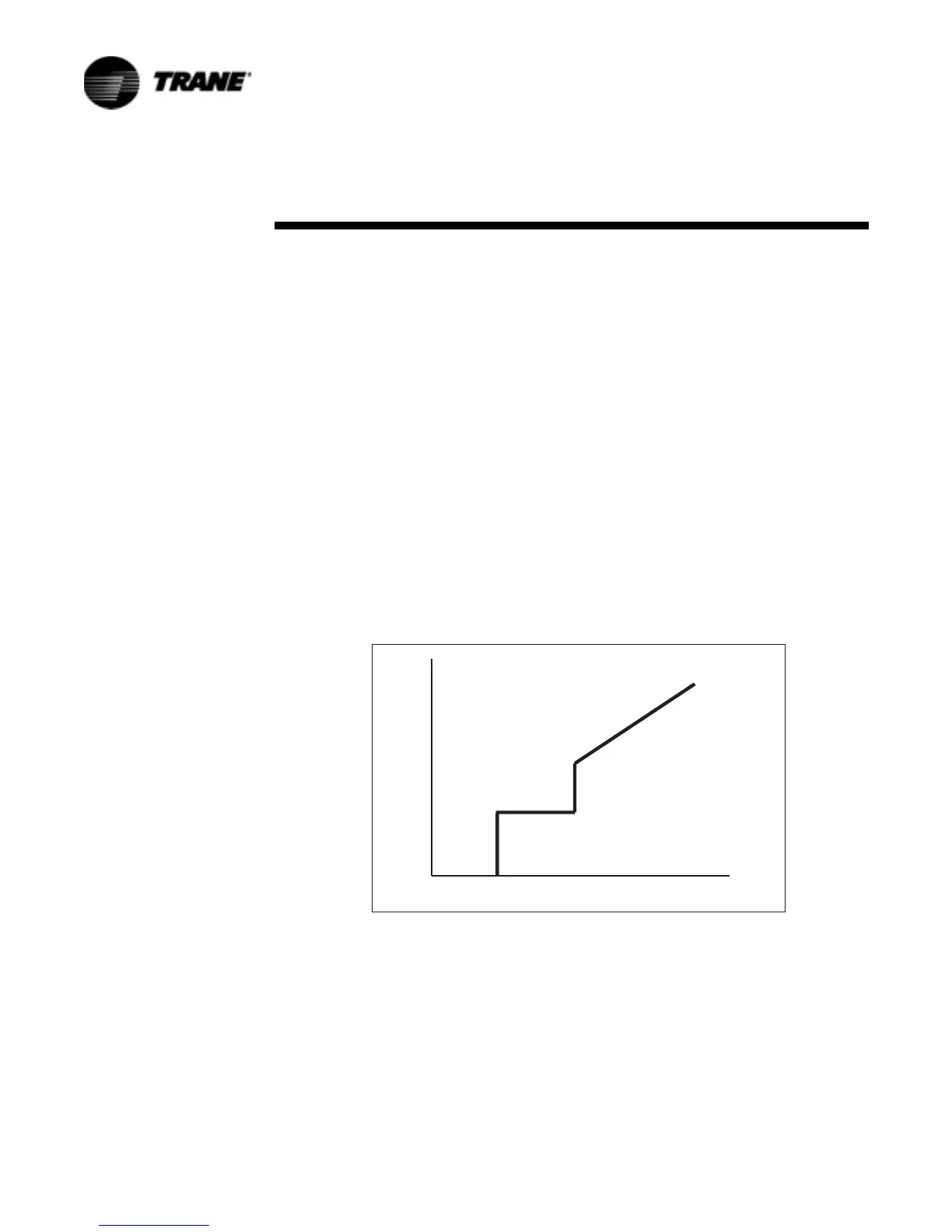
With the female solenoid de-energized (internal female bypass valve open), the
minimum capacity of the compressor is 30% of full load. With the female
solenoid valve energized, (and the male port unloader in the unloaded position)
the compressor capacity jumps up to approximately 60%. Through pulsed
control of the male load and unload solenoid valves, the piston can be moved to
exactly modulate the load of the compressor from 60 to 100% of its capacity.
There are no springs acting on the male port unloader piston, and as such, the
piston can only be effectively moved while the compressor (or manifolded
compressor) is running, creating differential pressure.
Compressor Capacity - RTAC
Figure 32.Compressor Capacity
#APACITY
OFF
ON
STEP
-ODULATE
4IME
 Loading...


