Installation Electrical
RTAF-SVX001A-EN 31
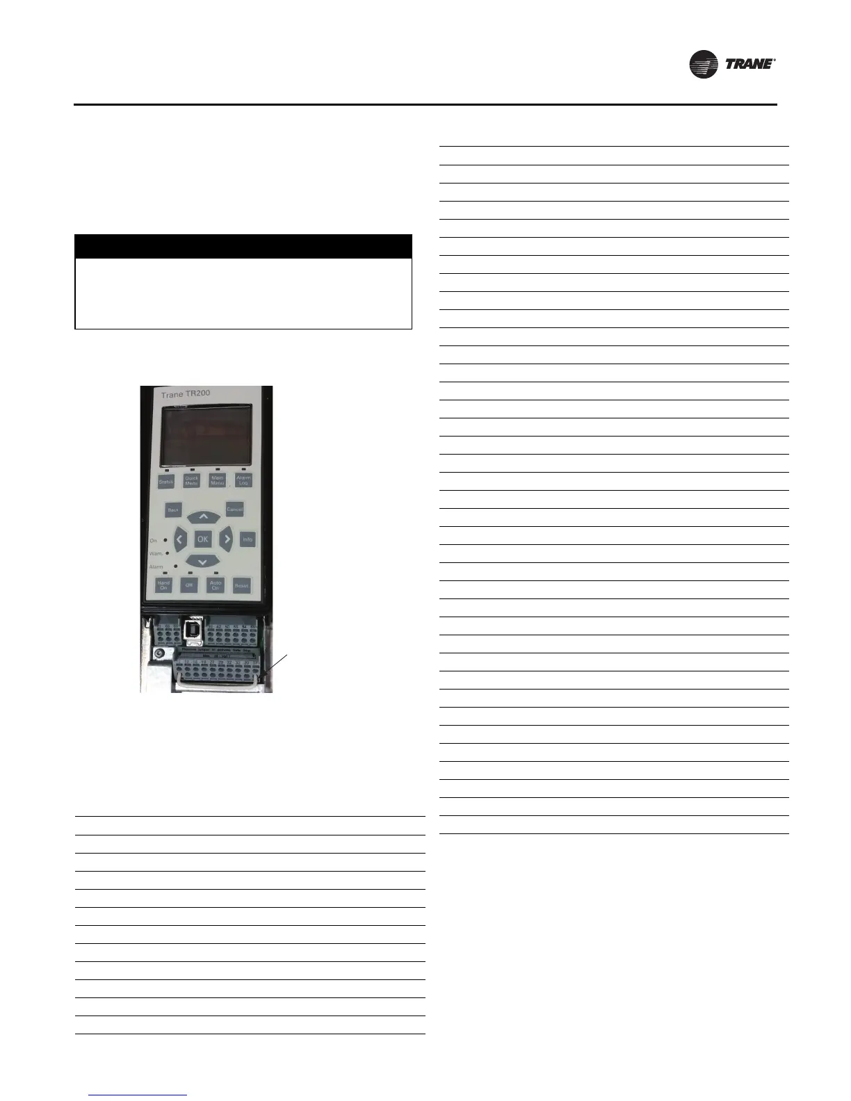
AFD Drive Installation
The AFD drive is manufactured with a jumper installed
between terminal 12 (+24Vdc source) and terminal 37
(Safe Stop digital input).This jumper must be removed
prior to unit operation. See Figure 14 for view of jumper as
it would be installed on drive from manufacturer.
AFD Drive Programming
Field replacement drives must be programmed via the
keypad interface. Program parameters sequentially by ID
values as defined in Table 14 and Table 15, p. 32.
NOTICE:
Equipment Damage!
Verify/remove jumper between AFD terminals 12 and
37 before unit operation. Failure to remove jumper
could cause equipment damage.
Figure 14. AFD jumper
Table 14. Non-compressor specific parameter settings
ID Description Setting
0-03 Region Settings [1] North American
0-20 Display Line 1.1 Small [1612] Motor Voltage
0-24 Display Line 3 Large [1617] Speed (rpm)
0-40 [Hand on] Key on LCP [0] Disabled
0-41 [Off] Key on LCP [0] Disabled
0-60 Main Menu Password 999
0-61 Access to Main Menu w/o Password [1] LCP: Read-only
1-03 Torque Characteristics [0] Compressor Torque
1-21 Motor Power [HP] See Table 15
1-22 Motor Voltage See Table 15
1-23 Motor Frequency 60Hz
Jumper between
terminals 12 and 37
must be removed
prior to unit
operation.
1-24 Motor Current See Table 15
1-25 Motor Nominal Speed See Table 15
1-71 Start Delay 0s
1-73 Flying Start [0] Disabled
1-78 Compressor Start Max Speed [Hz] 30Hz
1-79 Compressor Start Max Time to Trip 10s
1-82 Min Speed for Function at Stop [Hz] 10Hz
1-87 Trip Speed Low [Hz] 25Hz
3-02 Minimum Reference 30Hz
3-41 Ramp 1 Ramp Up Time 5s
3-42 Ramp 1 Ramp Down Time 5s
3-82 Starting Ramp Up Time 3s
4-10 Motor Speed Direction [0] Clockwise
4-12 Motor Speed Low Limit [Hz] 30Hz
4-18 Current LImit 116.7%
4-19 Max Output Frequency 61Hz
5-12 Terminal 27 Digital Input [2] Coast Inverse
5-13 Terminal 29 Digital Input [0] No Operation
5-40.0 Function Relay 1 [5] Running
5-40.1 Function Relay 2 [3] Drive Rdy/Rem Ctrl
5-41.0 On Delay, Relay 1 1s
5-41.1 On Delay, Relay 2 1s
5-42.0 Off Delay, Relay 1 1s
5-42.1 Off Delay, Relay 2 1s
6-10 Terminal 53 Low Voltage 2V
6-14 Terminal 53 Low Ref./Feedb. Value 30Hz
6-50 Terminal 42 Output [133] Motor Cur. 4-20mA
14-03 Overmodulation [0] Off
14-10 Mains Failure [4] Kinetic Back-up
14-11 Mains Voltage at Mains Fault See Table 15
14-20 Reset Mode [1] Automatic Reset x 1
14-30 Current Lim Ctrl. Proportional Gain 25%
14-31 Current Lim Ctrl. Integration Time 1s
14-50 RFI Filter [0] Off
14-51 DC Link Compensation [1] On
22-75 Short Cycle Protection [1] Enabled
22-76 Interval Between Starts 60s
Table 14. Non-compressor specific parameter settings
ID Description Setting
 Loading...

