RTAF-SVX001A-EN 35
Controls
Overview
Sintesis™ RTAF chillers utilize the following control/
interface components:
• Tracer™ UC800 Controller
• Tracer AdaptiView™TD7 Operator Interface
UC800 Specifications
This section covers information pertaining to the UC800
controller hardware.
Wiring and Port Descriptions
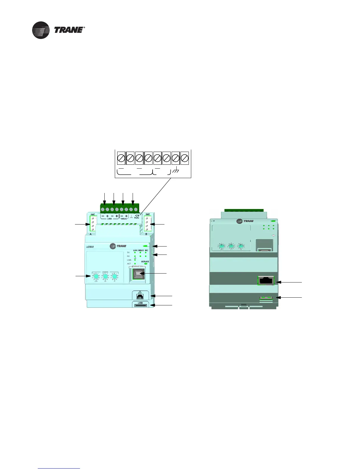
Figure 16 illustrates the UC800 controller ports, LEDs,
rotary switches, and wiring terminals.The numbered list
following Figure 16 corresponds to the numbered callouts
in the illustration.
Figure 16. Wiring locations and connection ports
1. Rotary Switches for setting BACnet
®
MAC address or MODBUS ID.
2. LINK for BACnet MS/TP, or MODBUS Slave (two terminals, ±). Field wired if used.
3. LINK for BACnet MS/TP, or MODBUS Slave (two terminals, ±). Field wired if used.
4. Machine bus for existing machine LLIDs (IPC3Tracer bus 19.200 baud). IPC3 Bus: used for Comm4 usingTCI or LonTalk
®
using LCI-C.
5. Power (210 mA at 24 Vdc) and ground terminations (same bus as item 4). Factory wired.
6. Not used.
7. Marquee LED power and UC800 Status indicator (Table 16, p. 36).
8. Status LEDs for the BAS link, MBus link, and IMC link.
9. USB device type B connection for the service tool (Tracer TU).
10. The Ethernet connection can only be used with theTracer AdaptiView display.
11. USB Host (not used).
LINK
+ +
+
24
VDC
+
MBUS
Front View
6
7
8
9
6
1
10
11
234 5
Bottom View
10
11
 Loading...

