21
Section 10. Refrigerant Line
10.1 Refrigerant Line Connection Sizes
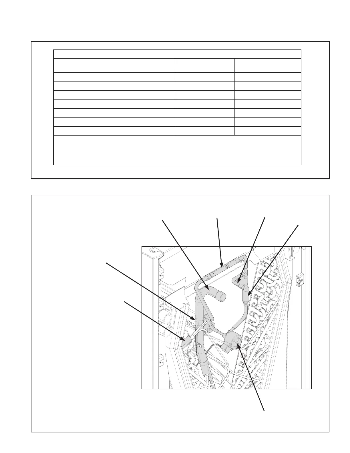
10.2 Refrigerant System Layout
Refrigerant Line Set and Connection Sizes
Model
Vapor Line
Connection
Liquid Line
Connection
TAM4A0A18S11ED, TAM4A0A18S11SD
3/4 3/8
TAM4A0A24S21ED, TAM4A0A24S21SD
3/4 3/8
TAM4A0A30S21ED, TAM4A0A30S21SD
3/4 3/8
TAM4A0A36S31ED, TAM4A0A36S31SD
3/4 3/8
TAM4A0B42S31ED, TAM4A0B42S31SD
7/8 3/8
TAM4A0C48S41ED, TAM4A0C48S41SD
7/8 3/8
TAM4A0C60S51ED, TAM4A0C60S51SD
7/8 3/8
Note: All AHRI listed systems which are inclusive of the above fan coil units were tested with 25
feet of tubing. The rated tubing diameters are listed in the above tables. However, if refrigeration
lines exceed 60 feet, and / or if alternate size existing refrigeration lines are present at the job
site, please consult SS-APG006-EN or 32-3312-** ( latest version).
Table 10.1
EEV Stepper Motor
Vapor Line
Liquid Line
Check Valve
Strainer
Note: Some future models
may not have external check
valve.
Evaporator Temperature
Sensor (ET)
- located on 3/8" Aluminum
distributor tube
(orange wires)
Gas Temperature
Sensor (GT)
- located on copper
section of manifold
(black wires)
 Loading...