Installer’s Guide
13
If an exhaust fan, additional air consuming machines
(e.g. an air compressor), or a return air grill is present
in the furnace room, there should be increased concern
about providing adequate airflow to the furnace. Addi
-
tional efforts may be required to assure an adequate
supply of combustion and ventilation air is available to
the furnace under all conditions.
CHIMNEY INSPECTION
The chimney, vent, or any passageway for the stack
gases to flow to the outdoor atmosphere is a very im
-
portant part of the heating system. No furnace, regard-
less of the efficiency of the design, can perform satis-
factorily when the chimney to which it is connected is
inadequate or in poor condition.
Any of the following symptoms may indicate a chimney
has severe structural damage and is unsuitable for use:
- Chimney appears to be leaning to the side.
- Chimney appears to have structural damage, i.e.
loose or missing blocks or bricks, or excessive deterio-
ration at mortar joints.
- Tile liner damaged or missing.
- Flue gas leakage along the length of the chimney be-
tween the chimney connector and discharge termina-
tion.
- Excessive corrosion at the cleanout port or at the
chimney connector entrance into the chimney.
- Structural debris, i.e. mortar or tile liner flakes, in
base of the flue way.
A qualified person shall inspect the chimney to confirm
it is correctly sized for the application, properly con
-
structed, and in sound condition. Refer to the Stan-
dard for the Installation of Oil-Burning Equipment,
NFPA 31-2001, for details on proper chimney sizing
and construction. If needed, the chimney should be
cleaned before installing the furnace. Any accumula
-
tion of dirt or debris at the bottom of the flue should be
removed.
CHIMNEY SIZING:
The furnace must be connected to an adequate chim
-
ney or an approved vent in accordance with these in-
structions. An adequate chimney is one that is sealed
and lined with the capability of producing a (-).04"
WC flue draft and having the capacity to handle the
amount of stack gases that are introduced into it. A
chimney with an internal construction of corrosion re
-
sistant tile, stainless steel, or some other material that
will withstand flue gas temperatures up to 900°F is re
-
quired.
The following are common chimney requirements
necessary for the furnace to operate correctly:
A masonry chimney serving an oil fired furnace must
comply with local codes and NFPA Standard for Chim
-
neys, Fireplaces, Vents, and Solid Fuel Burning Appli-
ances (NFPA211-1996 or latest edition).
All installations and services must be performed
by qualified service personnel.
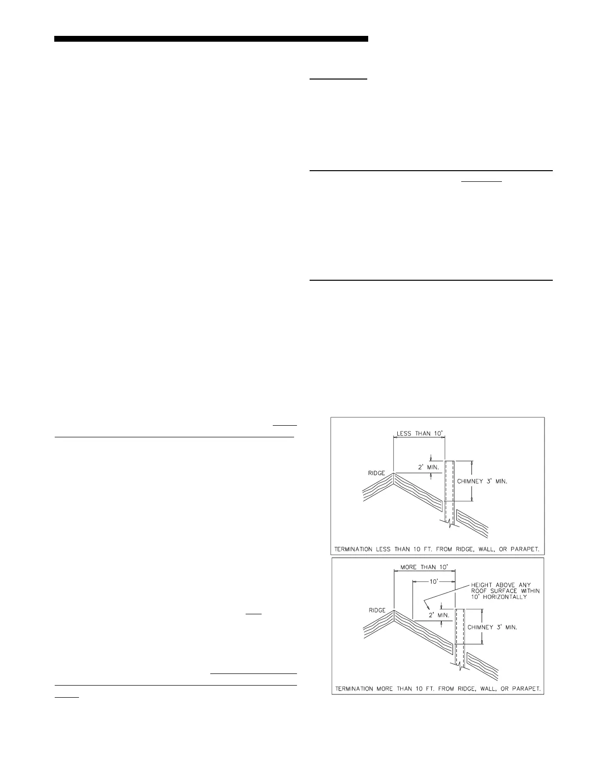
3URSHUFKLPQH\WHUPLQDWLRQKHLJKW
IRUSLWFKHGURRIV
The inside area of the chimney liner should equal,
at minimum, the area of the vent pipe exiting the
furnace-
EXAMPLE: π x r
2
= Area of Pipe (sq. in.)
r = radius of pipe
π = 3.1417
Flue Pipe Diameter = 6" [Radius of pipe = ½
diameter of pipe = ½ ( (6 in.) = 3in.]
π x 3
2
= 28 sq. in.
NOTE: This formula calculates the minimum inside area
of the chimney. If more than one appliance vent con-
nector pipe is connected to the chimney, the minimum
inside area of the chimney should be equal to the area
of the largest vent pipe plus one half the area of any
additional vent pipes. If the chimney is too large or
condensation has been a problem in the past refer to
the NFPA Standard for the Installation of Oil Burning
Equipment (NFPA31-1997 or latest edition) Appendix E
for proper liner sizing.
CHIMNEY HEIGHT:
The chimney shall terminate at least 3 feet above the
highest point where it passes through the roof of a
building and at least 2 feet higher than any portion of
a building within a horizontal distance of 10 feet. (See
Fig. 5a).
If the chimney penetrates a roof more than 10 feet
from a ridge, wall or parapet, a minimum of 3 feet
above roof or exit point must be maintained. See
Figure 5b.
5
 Loading...