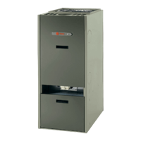
Installer’s Guide
3
Contents
CONTENTS
INSTALLATION GUIDELINES 2
Location 2
Clearances 4
Downflow/ Horizontal Furnace Setup 4
Air for Combustion and Ventilation 5
Chimney Inspection 13
Chimney Sizing 13
Chimney Height 13
Flue/ Chimney/ Vent Connector 14
Draft Regulator 16
Power (Side-Wall) Venting 16
Duct Work and Air Conditioning 17
Air Filter Mounting 17
Oil Burner and Oil Nozzle Installation 18
Fuel System Installation 19
Electrical Connections 20
8. The furnace may be used for temporary heating
of buildings or structures under construction only
when the following conditions have been met:
a. The furnace venting system must be complete
and installed per manufacturers instructions.
b. The furnace is controlled only by a room thermo
-
stat (no field jumpers).
c. The furnace return air duct must be complete
and sealed to the furnace and clean air filters
are in place.
d. The furnace input rate and temperature rise
must be verified to be within nameplate mark
-
ing.
e. 100% of the furnace combustion air requirement
must come from outside the structure.
f. The furnace return air temperature range is be
-
tween 70 and 100 degrees Fahrenheit.
g. Clean the furnace, duct work, and components
upon substantial completion of the construction
process, and verify furnace operating conditions
including ignition, input rate, temperature rise
and venting, according to the manufacturer's in
-
structions.
The manufacturer of this equipment assumes no liabili-
ty for any damages resulting from unauthorized modifi-
cations made to the furnace, or any components there-
of, or improper installation of the furnace in the field.
Furthermore, any such field modifications VOID THE
WARRANTY and place responsibility for safe and reli-
able operation of the furnace on those who performed
the modification(s).
INSTALLATION GUIDELINES CODES
All local codes and regulations take precedence over
the instructions in this manual and shall be followed
accordingly. In the absence of local codes, this instal
-
lation must conform to these instructions and to the
regulations of the National Fire Protection Association
(NFPA) publications, the Standard for the Installation
of Oil-Burning Equipment, NFPA 31-2001, and the Na
-
tional Electrical Code, ANSI/NFPA 70-2002, or the lat-
est editions thereof.
INSTALLATION LOCATION
To prevent shortening its service life, the furnace
should not be used as a “Construction Heater” during
the finishing phases of construction until the require-
ments listed in item 8, a-g of the safety section of this
publication have been met. Condensate in the presence
of chlorides and fluorides from paint, varnish, stains,
adhesives, cleaning compounds, and cement create a
corrosive condition which may cause rapid deteriora-
tion of the heat exchanger.
SUPPORT FURNACE PROPERLY
DO NOT hang the downflow/ horizontal furnace from a
structure, or surface, by any integral part or fastener of
the furnace. The furnace was not designed to support
itself in this manner.
In as much as practical, the furnace should be posi-
tioned near a chimney or vent and should be central-
ized with respect to the air distribution system.
For a utility room installation, the entrance door must
be wide enough to permit the largest part of the fur
-
nace to pass through the doorway or allow sufficient
clearance to permit the replacement of another appli
-
ance, e.g. a water heater, in the room.
If the furnace is installed in a residential garage, it
must be installed so the burner is located higher than
18 inches above the floor. Also, the furnace must be lo
-
cated or protected to avoid physical damage from im-
pacts by vehicles.
Highboy and lowboy furnace models must rest on stur
-
dy, stable, and level surfaces.
The downflow/ horizontal model may be mounted on
a level surface, as described above, or it may be sus
-
pended from an overhead structure or surface. If this
model is suspended from hanger rods, support the
furnace from the bottom casing surface at three
(3) places, across both ends of the casing and across
the casing, near the middle of the furnace.
Generally, a simple support frame for the furnace can
be fabricated from structural steel angle, threaded
steel rod, and fastener hardware, refer to Figure 1. Ad
-
just the height of the support angles to level the unit
in position.
 Loading...


