Installer’s Guide
4
STANDARD CLEARANCES
Standard clearances are mandatory minimum clear-
ances from heated surfaces of the furnace to combusti-
ble materials to assure protection from fire hazard dur-
ing furnace operation. (Refer to the Standard for the
Installation of Oil-Burning Equipment, NFPA 31-2001,
for definitions of combustible and non-combustible ma
-
terials.)
Accessibility clearances, which are typically greater,
may exceed fire protection clearances. Therefore, con
-
sider providing at least 24 inches of clearance from the
front (and the rear, for lowboy furnaces) of the furnace
to obstructions and surfaces for adequate service and
maintenance access.
CLOSET AND ALCOVE INSTALLATION
All furnace models may be installed in a closet or al-
cove on combustible flooring with specified (standard)
clearances to combustible construction.
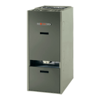
The horizontal/ downflow furnace model re
-
quires an optional combustible surface-mounting
base (model # BAYSUB10ABASEAA) for vertical
installation (i.e., downflow configuration) direct
-
ly on combustible materials, refer to Figure 2.
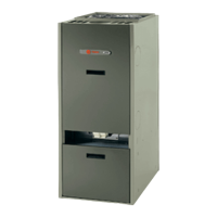
1
Recommended Support Frame for Downflow/
Horizontal Furnaces
2
Downflow Furnace Combustible
Surface-Mounting Base
The minimum clearances from furnace casing
surfaces to combustible materials are:
- 3 inches from casing sides and rear
- 8 inches from front casing of furnace to the closet
door, with exception of:
* The lowboy rear flue model only requires 3 inches
from front casing of the furnace to the closet door.
* The downflow/ horizontal furnace requires 22
inches from front casing of the furnace to the closet
door.
- 9 inches from flue pipe/ vent connector.
- 3 inches from casing top.
- 3 inches from any side of supply air plenum.
- 3 inches above supply air ducts, within 6 feet of fur
-
nace.
- For the downflow/ horizontal furnace only,
when the optional combustible surface-mounting
base is used with the furnace in the downflow con
-
figuration, adequate clearances from the supply end
surface of the furnace casing to combustible surfaces
are provided by the design of the mounting base.
Though these are approved clearances for these fur
-
naces, space must be provided at the front (18 inches
minimum, 24 inches recommended) and at the rear of
the furnace for access, service, and replacement of the
oil burner, air filter(s), circulating air blower, and fan
motor.
DOWNFLOW/ HORIZONTAL FURNACE
SETUP
The downflow/ horizontal furnace is shipped from the
factory upright for vertical installation (downflow con
-
figuration). If the furnace is to be installed lying down
on the right-hand or left-hand side (horizontal configu
-
ration), the positions of the oil burner and the fan and
limit control thermostat may have to be changed. See
Figure 3.
The horizontal furnace may be turned end for end, or
rotated, making the top into the bottom, as shown in
Figure 3. Refer to the following instructions for install
-
ing the oil burner and thermostat.
Note: See Illustration on page 24 for the
dimensions of the mounting base.
 Loading...