Installer’s Guide
20
• Install a generous capacity filter inside the build-
ing between the fuel tank shutoff valve and the
burner, locating both the filter and the valve close to
the burner for ease of servicing. Filter should be
rated for 50 microns or less.
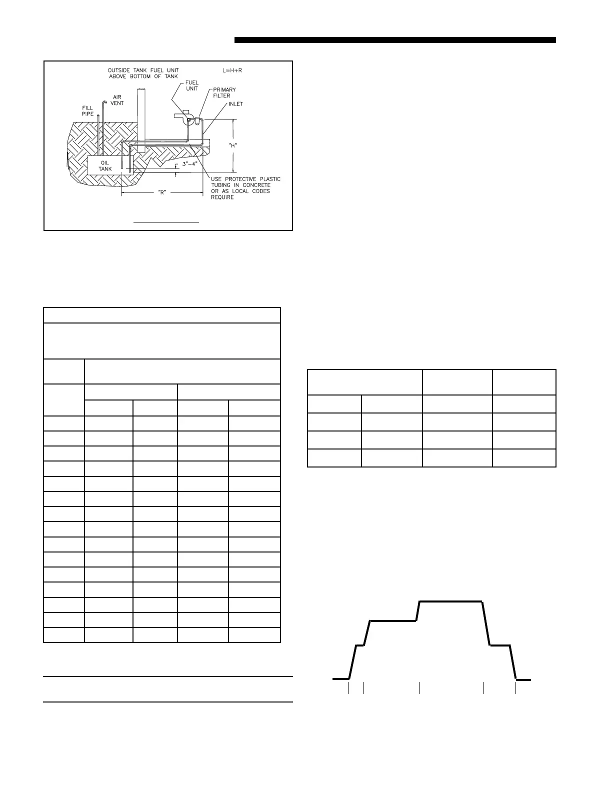
The following table and graph explain the delay-off set-
tings:
COOLING OFF - DELAY OPTIONS
SWITCH SETTINGS SELECTION
NOMINAL
AIRFLOW
5 - OFF 6 - OFF NONE SAME
5 - ON 6 - OFF 1.5 MINUTES 100% *
5 - OFF 6 - ON 3 MINUTES 50%
5 - ON 6 - ON ** 50 - 100%
TABLE 1
SINGLE STAGE, TWO PIPE
MAXIMUM LINE LENGTH
( H + R )
3450 RPM
Lift
"H"
3/8" Tubing 1/2" Tubing
3 GPH 7 GPH 3 GPH 7 GPH
0' 84' 71' 100' 100'
1' 78' 66' 100' 100'
2' 73' 62' 100' 100'
3' 68' 57' 100' 100'
4' 63' 53' 100' 100'
5 57' 48' 100' 100'
6' 52' 44' 100' 100'
7' 47' 39' 100' 100'
8' 42' 35' 100' 100'
9' 36' 31' 100' 100'
10' 31' 27' 100' 100'
11' 26' 22' 100' 87'
12' 21' 18' 83' 70'
13' - - 62' 52'
14' - - 41' 35'
VARIABLE SPEED DIP SWITCH SETTING FOR COOLING
t
SEE TABLE 1
0N PAGE 18
ELECTRICAL CONNECTIONS
NOTICE: All field wiring must conform to local, state,
and national installation codes.
A disconnect switch equipped with overcurrent protec-
tion (e.g. a time delay-type fuse or inverse time, cir-
cuit breaker) should be installed in the service line for
shutting down and protecting the furnace and electri
-
cal system.
Since the furnace is entirely pre-wired at the factory, it
is only necessary to connect the building electrical ser
-
vice lines to the two (2) pigtail wires extending from
the fan center junction box. The fan center is mounted
inside the furnace burner compartment or mounted
on the front exterior of the furnace, in the case of the
downflow / horizontal model. The service lines to the
furnace should be no smaller than 14 Ga., insulat
-
ed copper wire with a temperature rating of 60ºC, or
greater.
Connect an equipment ground wire to the furnace at
the fan center junction box. If wiring is run through
metal electrical conduit, it may not be necessary to run
a separate equipment ground wire. Consult local codes
and authorities for specific minimum requirements.
* - This setting is equivalent to BAY24X045 relay ben-
efit.
** - This selection provides ENHANCED MODE, which
is a ramping up and ramping down of the blower
speed to provide improved comfort, quietness,
and potential energy savings. See Service Facts
for cooling and heating air flow dip switch settings
1,2,3,4,7,8. The graph which follows, shows the
ramping process.
OFF
50%
50%
80%
Dehumidify
Efficiency
Fast Cooling
1
minute
3
minutes
7.5
minutes
100% if necessary
OFF
See Service Facts for dip switch setting
for complete setup for Enhanced Mode.
 Loading...