Installer’s Guide
17
Two (2) problems typically arise when power venting
any oil fired appliance:
1) Soot buildup may occur at an accelerated rate on
critical components of the furnace oil burner, e.g.
the primary control flame sensor (“cad cell”), the
burner head, and oil nozzle.
2) Severe damage may occur to external surfaces of
the structure in the event the furnace continually
produces a high level of smoke in the flue gases.
Excess smoke and soot can be produced for many
reasons, some of which cannot be successfully con
-
trolled by the installer and the appliance manufac-
turer.
NOTICE: The manufacturer recommends the use of a
chimney to vent residential oil furnaces. If a power ven-
ter must be used, it is the responsibility of the installer
and power venter manufacturer to design, assemble,
and demonstrate proper operation of the power vent-
ing system with the furnace.
DUCT WORK AND AIR CONDITIONING
Air duct systems should be installed in accordance
with standards for air conditioning systems, National
Fire Protection Association Pamphlet No. 90. They
should be sized in accordance with ACCA Manual D or
whichever is applicable.
All furnaces are tested over a range of external static
pressure that simulates the airflow resistance of the
ductwork, fittings, and diffusers connected to the fur
-
nace for a typical (average) duct system. The furnace
blower and blower motor have been selected to work
successfully against the following range of duct system
resistance.
Recommended range of duct system resistance for all
models: 0.2 to 0.5 in. W.G. external static pressure.
Due to the need to maintain an adequate supply of
combustion and ventilation air, the furnace shall not
be installed in a small room without a return air duct
system.
A duct the full size of the furnace return air opening
shall extend to a location outside the furnace room.
If the furnace is used in connection with cooling/ heat
pump systems, a 3 " minimum long transition must be
installed between the furnace supply air outlet and the
evaporator coil supply air inlet to prevent overheating
of the evaporator coil drain pan. See page 10 for spe
-
cific layout and dimensions.
OVERHEATING HAZARD!
Failure to maintain a minimum of 3" separation from
the furnace heat exchanger and the evaporator coil
drain pan may cause drain pan damage.
If the furnace is used in connection with summer air
conditioning (cooling), the furnace should be installed
in parallel with, or on the upstream side of, the evapo
-
rator coil to avoid water vapor condensation in the fur-
nace heat exchanger.
If the cooling unit is installed in a parallel flow ar
-
rangement, dampers (or other means used to control
airflow) should be provided to prevent chilled air from
entering the furnace. If such a damper is manually op
-
erated, it must be equipped with a means to prevent
operation of either unit, unless the damper is placed in
either the full heat or full cool position.
NOTICE: Return air grilles and supply registers in the
air distribution system should never be obstructed.
AIR FILTER MOUNTING
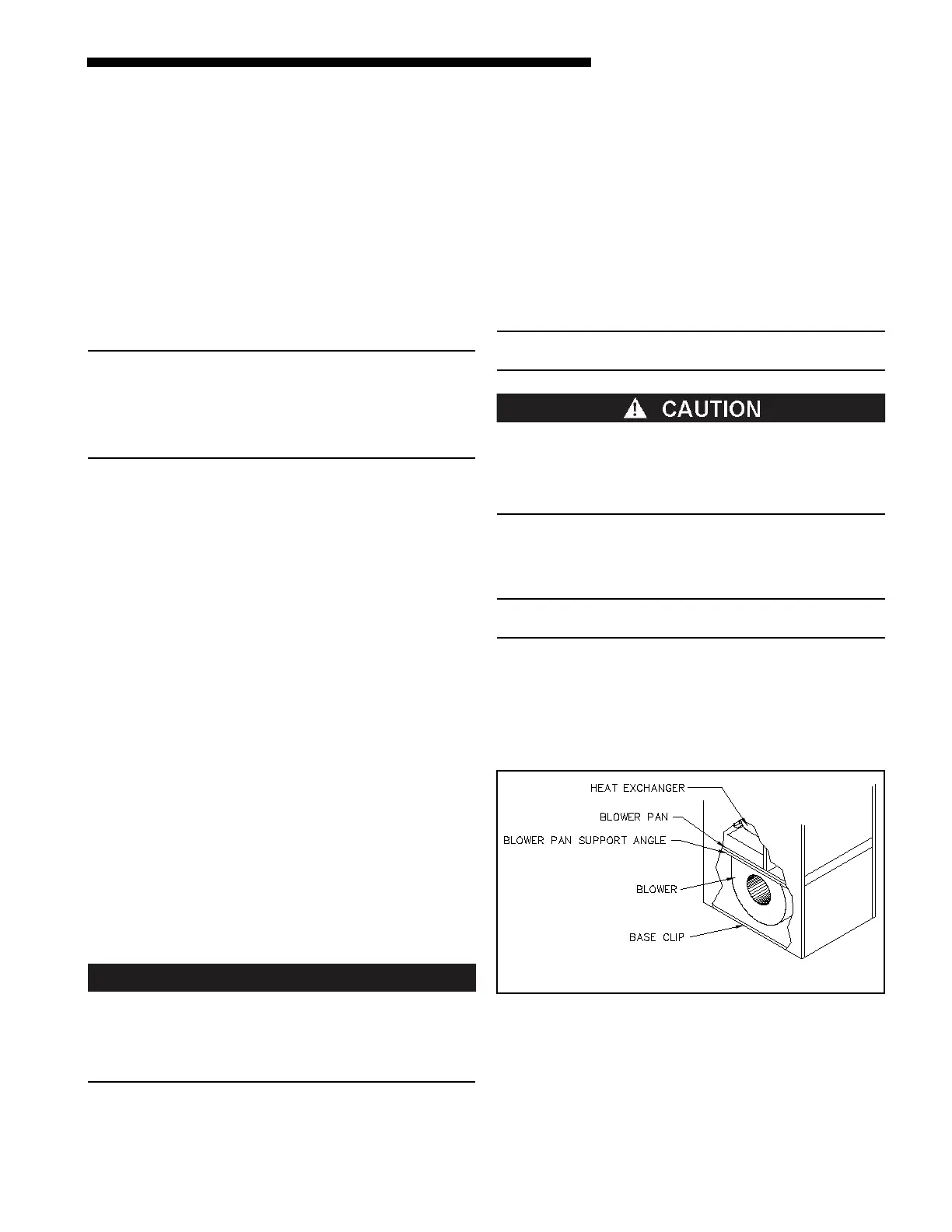
POSSIBLE CASING DAMAGE!
If cutting openings in the furnace casing is required,
DO NOT cut any supporting clips or angles. Cut as
close to the scribed line as possible, but DO NOT cut
the base clip or blower pan support angle.
Lowboy furnaces are factory-equipped with cleanable-
type, air filters located above the blower compartment,
in the rear of the furnaces. Highboy furnaces ship with
an external filter rack & cleanable-type filter.
NOTICE: Downflow/ horizontal furnaces are not factory-
equipped with an air filter or filter rack.
Furthermore, the furnace blower compartment does
not contain enough free space to permit an air filter to
be mounted within the furnace casing. The installer
should supply, or fabricate, a filter rack and mount an
air filter in the return air plenum above, or upstream
of, the furnace blower compartment.
w
Cutaway view of fan section
of a typical highboy furnace.
On the highboy furnace, it is necessary to cut the re-
turn air opening in the lower side, or rear, of the casing
depending upon the needs of the specific installation,
refer to Figure 12.
 Loading...