BAS-SVX46E-EN
13
Installing the Tracer Expansion Modules
This section provides installation information for the following:
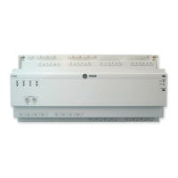
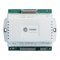
• Tracer XM30 Expansion Module
• Tracer XM32 Expansion Module
• Tracer XM70 Expansion Module
• Tracer XM90 Expansion Module
Expansion modules provide additional hardware terminations when needed for Tracer UC400
and Tracer UC600 applications. Each of the expansion modules listed above vary in the type and
capability of expansion; In some cases, additional Tracer PM014 DC power supply modules are
required (order number: S3090-0617-62).
Mounting and Removing Tracer Devices
Tracer unit controllers and expansion modules should be properly mounted on a DIN rail.
Control cabinets that include DIN rails are available from Trane.
To mount or remove the controller from the DIN rail, follow the illustrated instructions. If using a
DIN rail from another manufacturer, follow the recommended installation procedures that
accompany it.
IImmppoorrttaanntt:: When mounting the controller in a control cabinet, provide adequate spacing
between modules to allow for ventilation and heat dissipation.
NNOOTTIICCEE
EEnncclloossuurree DDaammaaggee!!
FFaaiilluurree ttoo ffoollllooww iinnssttrruuccttiioonnss bbeellooww ccoouulldd rreessuulltt iinn ddaammaaggee ttoo tthhee ppllaassttiicc eenncclloossuurree..
DDoo nnoott uussee eexxcceessssiivvee ffoorrccee ttoo iinnssttaallll tthhee ccoonnttrroolllleerr oonn tthhee DDIINN rraaiill.. IIff uussiinngg aannootthheerr
mmaannuuffaaccttuurreerr’’ss DDIINN rraaiill,, ffoollllooww tthheeiirr rreeccoommmmeennddeedd iinnssttaallllaattiioonn..
TToo mmoouunntt tthhee ddeevviiccee::
1. Hook device over top of DIN rail.
2. Gently push on lower half of device in the direction of arrow until the release clip clicks into
place.
TToo rreemmoovvee//rreeppoossiittiioonn tthhee ddeevviiccee::
3. Disconnect all connectors before removing or repositioning.
4. Insert screwdriver into slotted release clip and gently pry upward with the screwdriver to
disengage the clip.
5. While holding tension on the clip, lift device upward to remove or reposition.
If repositioned, push on the device until the release clip clicks back into place to secure the
device on the DIN rail.

 Loading...
