26
BAS-SVX46E-EN
Commissioning and Troubleshooting in a Powered
State
This section provides instructions for testing the expansion module points after establishing a
connection and applying power. The step numbers or method numbers in each figure
correspond to the information in each table.
The following equipment is required in order to test inputs and outputs:
• Digital multimeter (DMM)
• Small flat-bladed screwdriver
Resistive Inputs
Checkout Procedure
Measurement
Expected Value
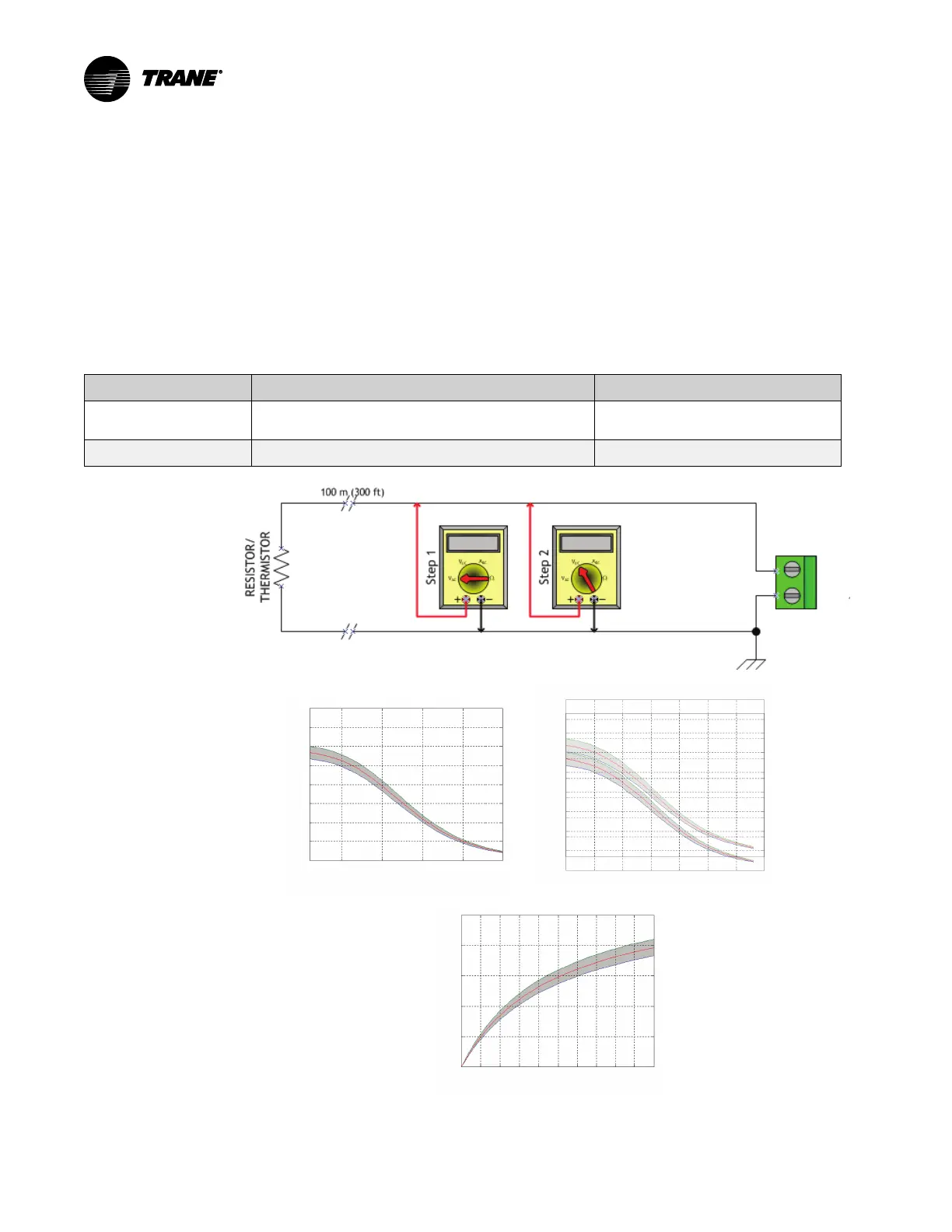
Step 1 Measure AC voltage across the resistive termination VAC ≈ 0.0 V
AC voltage will affect further measurement
Step 2 Measure DC voltage across the resistive termination Refer to the charts below
2.5
3
3.5
4
1.5
0
0.5
1
2
Meas ured Vo ltag e Acros s a Thermistor Inpu t
Voltage Mea sured Acros s In put–Vd c
Ther mist or Inpu t–°F
500 100 150 200
2.5
3
3.5
4
1.5
0
0.5
1
2
40-40 20-20 0 60 80 100
Voltage Me asu red Across Input–Vd c
Thermis tor Input–° C
Meas ure d Volt age Acr oss a Ther mis tor Input
Re sistive Inpu t–kΩ (Ohms)
Meas ured Vo ltag e Across a Re sistive Inpu t
Voltage Mea sure d Across In put–Vdc
10 1 24 60 2 16 1 88 2014
2.5
1.5
0
0.5
1
2
Charts show measurements
across thermistor input
(Fahrenheit and Celsius)
and resistive input.
 Loading...


