24
BAS-SVX46E-EN
Expansion Module Operation
After applying power to the expansion modules, the transmitting (TX) and receiving (RX) LEDs
blink when communication occurs between devices. The following table describes LED activity
and indicators.
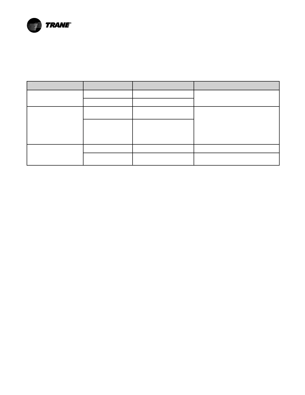
Table 9. LED identification and interpretation
LED type LED activity
Indicates...
Troubleshooting/Notes
Power
Solid green Normal operation
Sequence on power-up: Illuminates red,
then green.
Solid red
Low voltage or malfunction
Service
Solid green
LED has been pressed and
remains on until powered down
Sequence on power-up: One short blink
upon power-up or during memory test; will
remain green if memory test fails. When the
service LED is pressed, the module will
continue to use its normal node number for
communication. However, it will communicate
node 0 if possible (this does not affect
operation).
LED not illuminated
Normal operation
Binary outputs (BO1
through BO8)
Solid yellow Binary output is On/Energized.
LED not illuminated
Binary output is Off/De-
energized.
Troubleshooting
This section describes possible solutions for communication and status errors that may occur
after the modules have been configured (see “Configuring the Expansion Modules,” p. 22).
NNoottee:: By clicking the Discover Modules button, you can locate addresses of modules without
defining them.
Communication
PPrroobblleemm:
Points that are referencing expansion modules are in fault or not controlling.
SSoolluuttiioonn:
1. Verify that the expansion modules are powered.
2. Visually verify that all modules are communicating (both the TX and RX lights are blinking).
3. In Tracer TU, navigate to the UUttiilliittiieess//CCoonnttrroolllleerr//CCoonnttrroolllleerr SSttaattuuss screen.
4. In the Expansion Module Status section, confirm that all modules are communicating. After
clicking SSeenndd ttoo DDeevviiccee, if errors appear in the Errors column see “Status Errors” below.
Status Errors
Error messages that appear in the Tracer TU Expansion Module Status screen are explained
here.
 Loading...


