®
Chapter 1 Overview
6 BMTK-SVN01D-EN
Main module
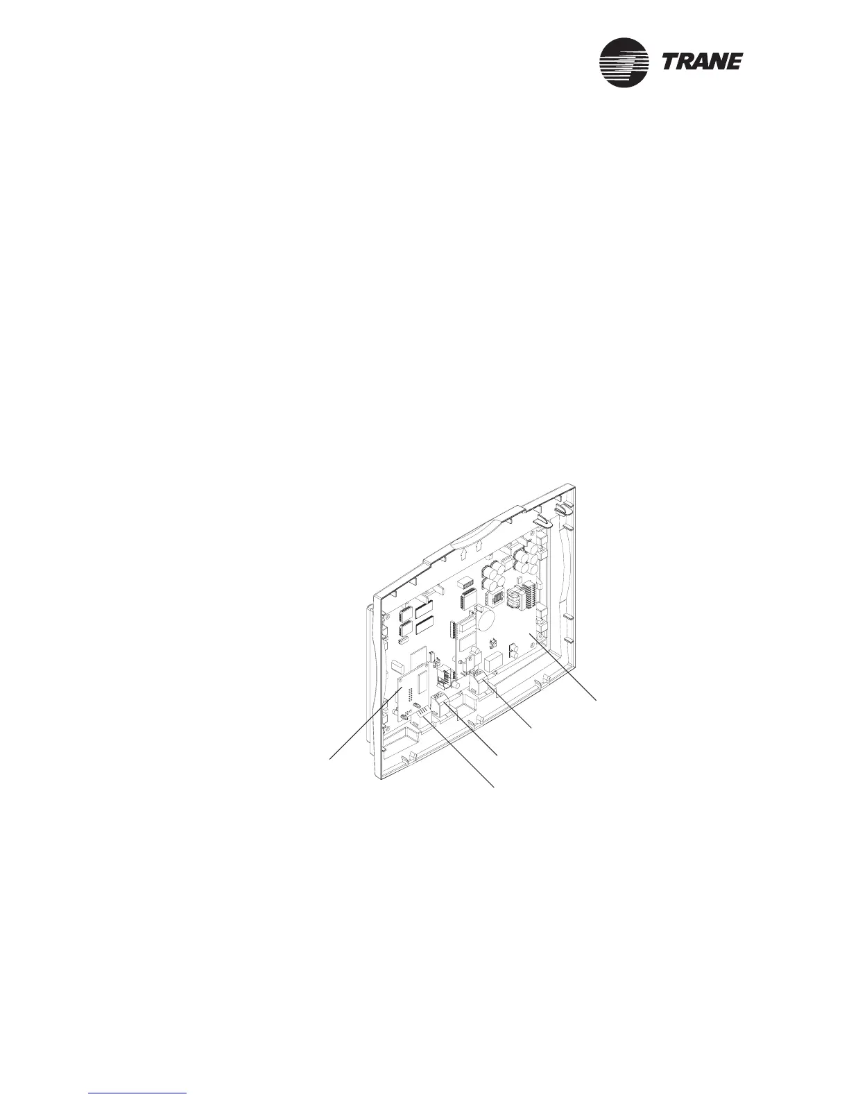
The main module (Figure 6) is a housing that contains the main logic
board and the Ethernet board. The main module can be “hot swapped”: it
can be removed and installed without removing power from the
termination module. When the main module is installed onto a powered
termination module, it receives power and begins to operate
automatically.
The main logic board provides an Ethernet LAN port, a PC interface port,
and a modem port. It provides an internal interface to termination
module I/O. It also provides Comm5 communication, 24 VAC power,
alarm, and communication indicators. It communicates and exchanges
data with the devices wired to the termination module. It also
communicates with the display module.
The Ethernet board provides two LED indicators. One shows that an
Ethernet link is detected; the other shows that there is serial traffic
between the Ethernet board and the main logic board.
Figure 6. Main module
Modem port
PC interface port
Ethernet LAN port
Main logic board
Ethernet
board
 Loading...