18 BAS-SVX40A-EN
Establishing the Network
On power-up, the WCI goes through a check list and updates LED activity according to the type of
device associated with the WCI and the status of the WCI in the network. The LED flash patterns
vary depending on current conditions. LED behavior is described in Ta bl e 2.
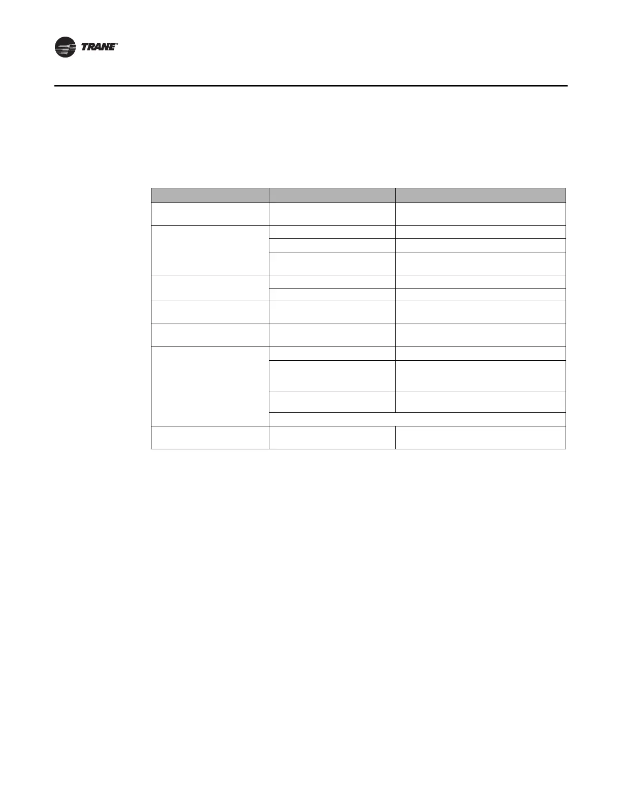
Table 2. LED identification and interpretation
LED
LED activity Indicates...
Network LED (green)
NWK
On solid WCI is a network member.
Sensor LED (green)
SNSR
Flashes Sensor has lost its association with the WCI.
On solid A sensor is associated with the WCI.
Coordinator LED (yellow)
CRD
On solid WCI is network coordinator.
Open Net LED (yellow)
OPEN NET
On solid Network is open for joining.
Off Network is closed.
Reception LED (yellow)
RX LINK
Flickers Data is being received.
Transmission LED (green)
TX LINK
Flickers Data is being transmitted.
Diagnostic LED (red)
DIAG
Flashes 50% on/off Hardware failure or failed re-flash of a radio.
Triple flash pattern. Occurs for 30
seconds after failing to join a
network.
WCI is not configured correctly by the unit
controller or IMC communication is down.
Double flash pattern
WCI lost MAC address on radios or WCI lost
ability to communicate with radio.
If more than one condition is present, the priority is in the order listed.
Power LED (green)
PWR
On solid WCI has power.

 Loading...