Dismantling Spring Wheel
DISMANTLING THE PLUNGER GUIDE BOX ASSEMBLY
P!unge;
Eiiide
Box. Remove the four outside bolts from the plunger guide box
and unscrew the two centre bolts sufficiently to enable the cases to be parted about
+"
(1.0
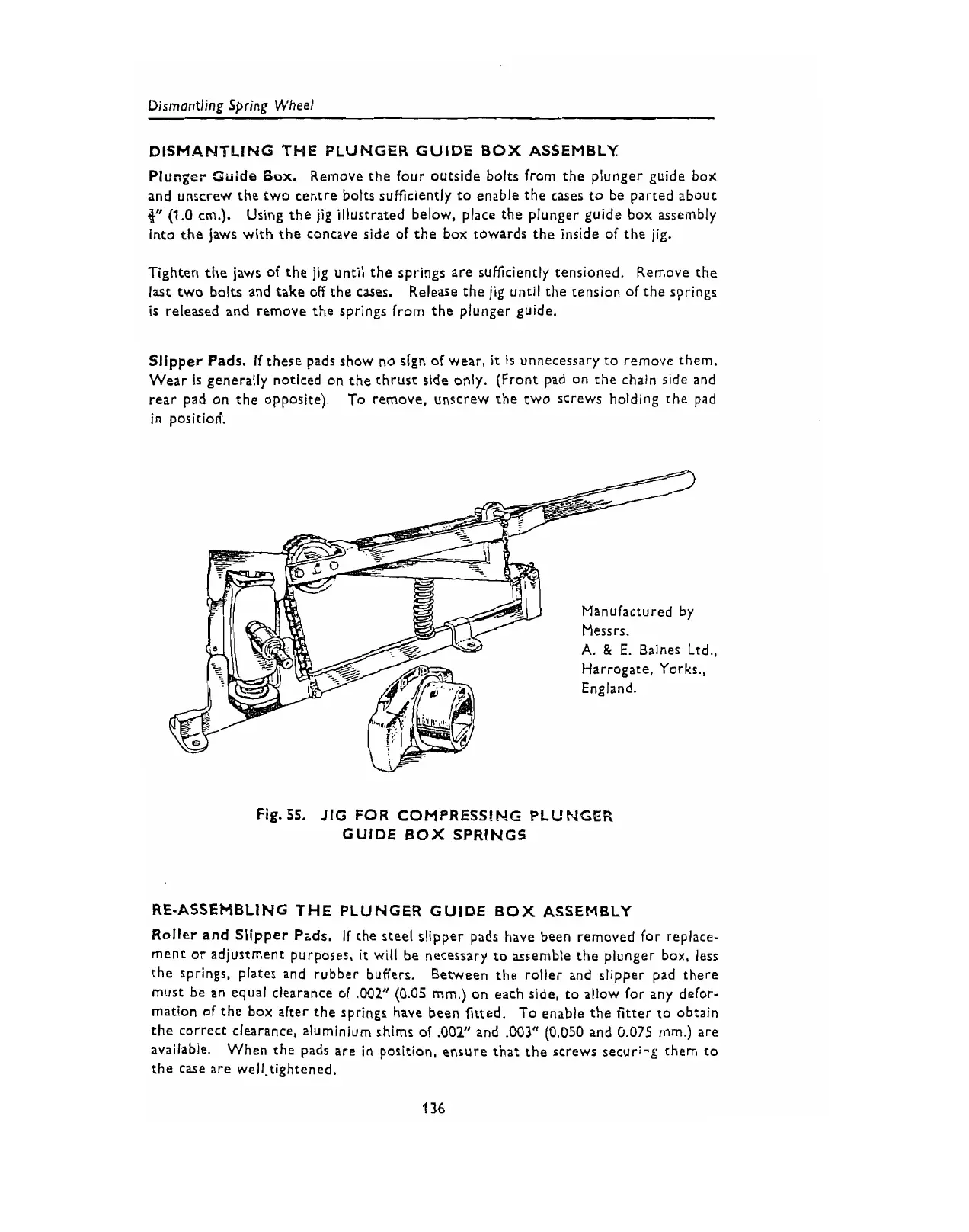
cm.). Using the jig illustrated below, place the plunger guide box assembly
into the jaws with the concave side of the box towards the inside of the jig.
Tighten the jaws of the jig until the springs are sufficiently tensioned. Remove the
last two bolts and take off the cases. Release the jig until the tension of the springs
is released and remove the springs from the plunger guide.
Slipper
Pads.
If these pads show no sign of wear,
it
is
unnecessary to remove them.
Wear
is
generally noticed on the thrust side only. (Front pad on the chain side and
rear pad on the opposite). To remove, unscrew the two screws holding the pad
in position'.
Manufactured by
Messrs.
A.
&
E.
Baines Ltd.,
Harrogate. Yorks.,
England.
Fig.
55.
JIG FOR COMPRESSING
PLUNGER
GUIDE BOX SPRINGS
RE-ASSEMBLING THE PLUNGER GUIDE
BOX
ASSEMBLY
Roller and Slipper Pzds. if the steel slipper pads have been removed for replace-
ment or adjustment purposes,
it
will be necessary to assemble the plunger box,
less
the springs, plates and rubber bilffers. Between the roller and slipper pad there
must be an equal clearance of
,002"
(0.05
mm.) on each side, to allow for any defor-
mation of the box alter the springs have been fitted. To enable the fitter to obtain
the correct clearance, aluminium shims of
.002"
and
,003"
(0.050
and
0.075
mm.) are
available. When the pads are in position, ensure that the screws securi-g them to
the case are well.tightened.
 Loading...