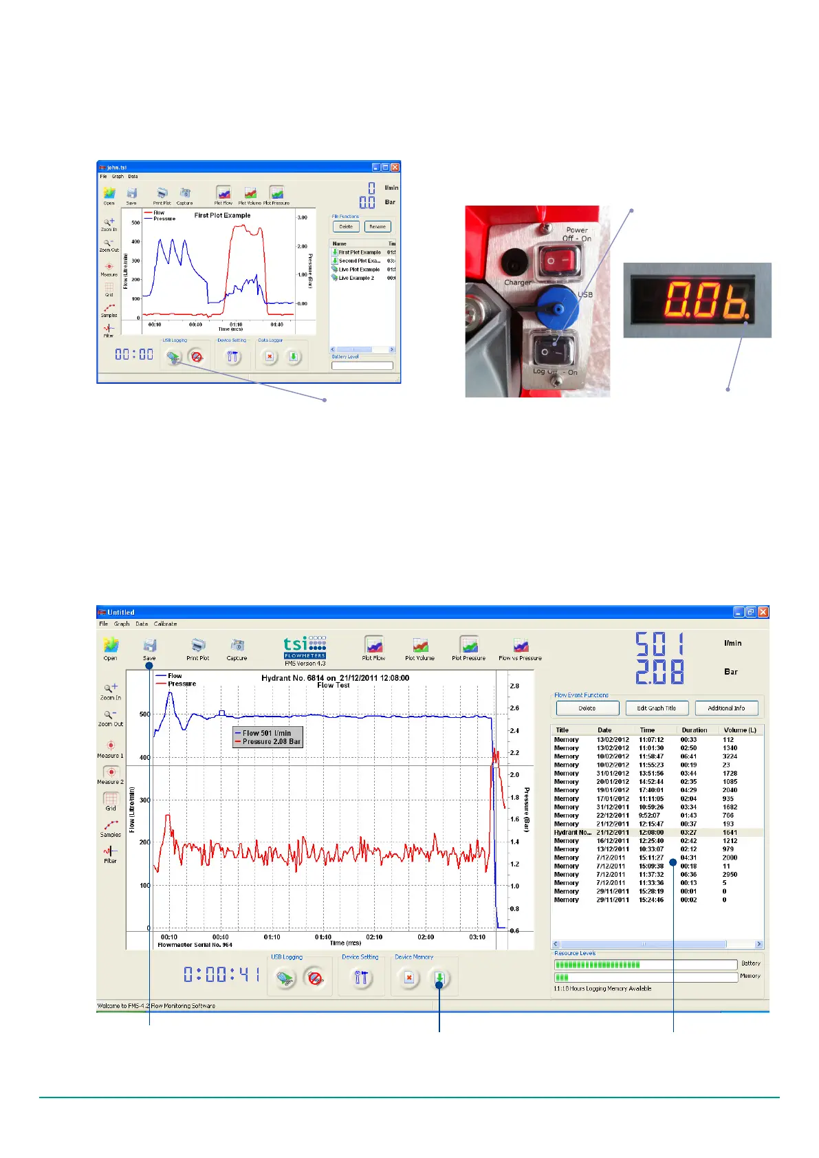
Fig. 4.17 Screen shot of user interface for the TSI Flow Monitoring software
Fig. 4.16 Activating data log. The picture on right hand
side shows that the logger is recording. This is indicated
by the orange ‘dot’ on the bottom right
Switch to control manual
data logging
Logger recording ‘dot’
The Flowmaster data logger can display error messages
about the status of the data logger and about the status
of the Flowmaster 250DL. These error messages are as
set out in Table 1.
Log Files
Use the Save button to save your
log les to computer hard drive
Data Upload button
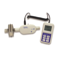
DATA LOGGING
The Flowmaster will log data as a stand-alone
instrument or directly to PC. Connect the Flowmaster
to your PC using the USB cable provided to live log.
Click the ‘USB Logging’ button on bottom of window
to begin data logging in live log mode.
4.5.2
When logging is in progress the recording ‘dot’ will light
up as shown in Fig. 4.16.
In manual mode, please press the black switch located at
the control panel of the Flowmaster to the ‘1’ position
to start logging ow and pressure. Take care that the
recording light is on. To stop logging, press the black
switch to the ‘0’ position.
In automatic mode, the logger will turn on and turn
off according to the ow rates and the conditions
established in software. The default activation ow rate
is 50 lpm and the default hysteresis ow rate is 30 lpm
continuously for ve seconds. Note, the recording light
will turn on when log conditions are met.
Fig. 4.14 Screenshot of FMS software with the live log
button highlighted
Live log button
The logger will store recorded data, even when the
meter is powered off.
Version 2.0 (February 2012) TSI Flowmeters Ltd.14
 Loading...