MAX-M10M-Integration manual
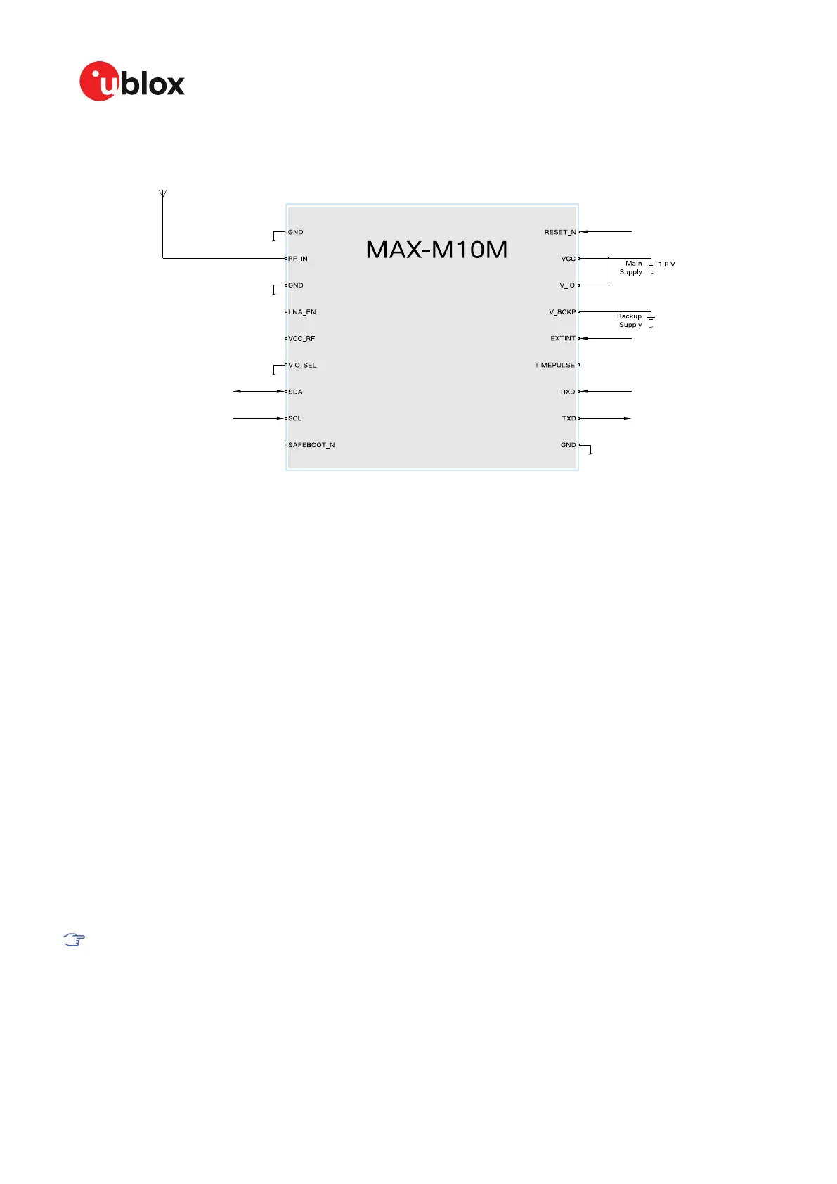
Figure 37: Typical 1.8 V design
B.2 Antenna supervisor designs
Figure 38 and Figure 39 show a reference design for a 2-pin and 3-pin antenna supervisor design
respectively. Here are some key features:
• VCC and V_IO are connected together to a single supply.
• Supply at V_BCKP is optional. If present, the hardware backup mode is supported. This mode
maintains the time and GNSS orbit data in the battery-backed RAM memory if the main supply
is switched off.
If there is no backup supply, time aiding with the UBX-MGA-INI-TIME_UTC message (optionally
with a timing signal at the EXTINT pin) and the GNSS orbit data from the AssistNow services or
stored on the host controller can be used to reduce the TTFF.
• An active antenna can be supplied with the VCC_RF output from MAX-M10M or from an external
supply. VCC_RF is a filtered output voltage supply, which outputs VCC - 0.1 V. In addition, the
active antenna supply can be turned on/off by the LNA_EN signal.
• External open drain buffers and operational amplifiers are also needed depending on whether a
2-pin or 3-pin antenna supervisor design is used.
• UART and I2C communication interfaces are available. I2C PIOs (SDA and SCL) can be used in a
3-pin antenna supervisor design as shown in Figure 39. In this case, the I2C interface needs to be
disabled before assigning the new function to the PIOs.
Disable the I2C interface with the CFG-I2C-ENABLED configuration key when I2C pins are used
for antenna supervisor functions. Likewise, disable the UART interface (CFG-UART1-ENABLED)
or TIMEPULSE (CFG-TP-TP1_ENA) when the pins are used for antenna supervisor functions.
UBX-22038241 - R02
Appendix Page 86 of 92
C1-Public

 Loading...


