(5) Probe Compensation
When the probe is connected to any input channel for the first time, this step might be required in order to match the probe
and the input channel. Please follow the following steps:
Set the attenuation coefficient in the probe menu and the switch on the probe to “10x”, and connect the probe to
CH1. Make sure the probe’s hook is properly connected with the oscilloscope. Connect the probe to the probe
compensation signal connector and connect the probe’s ground alligator clip to the ground terminal respectively.
Open CH1 and press the AUTO button.
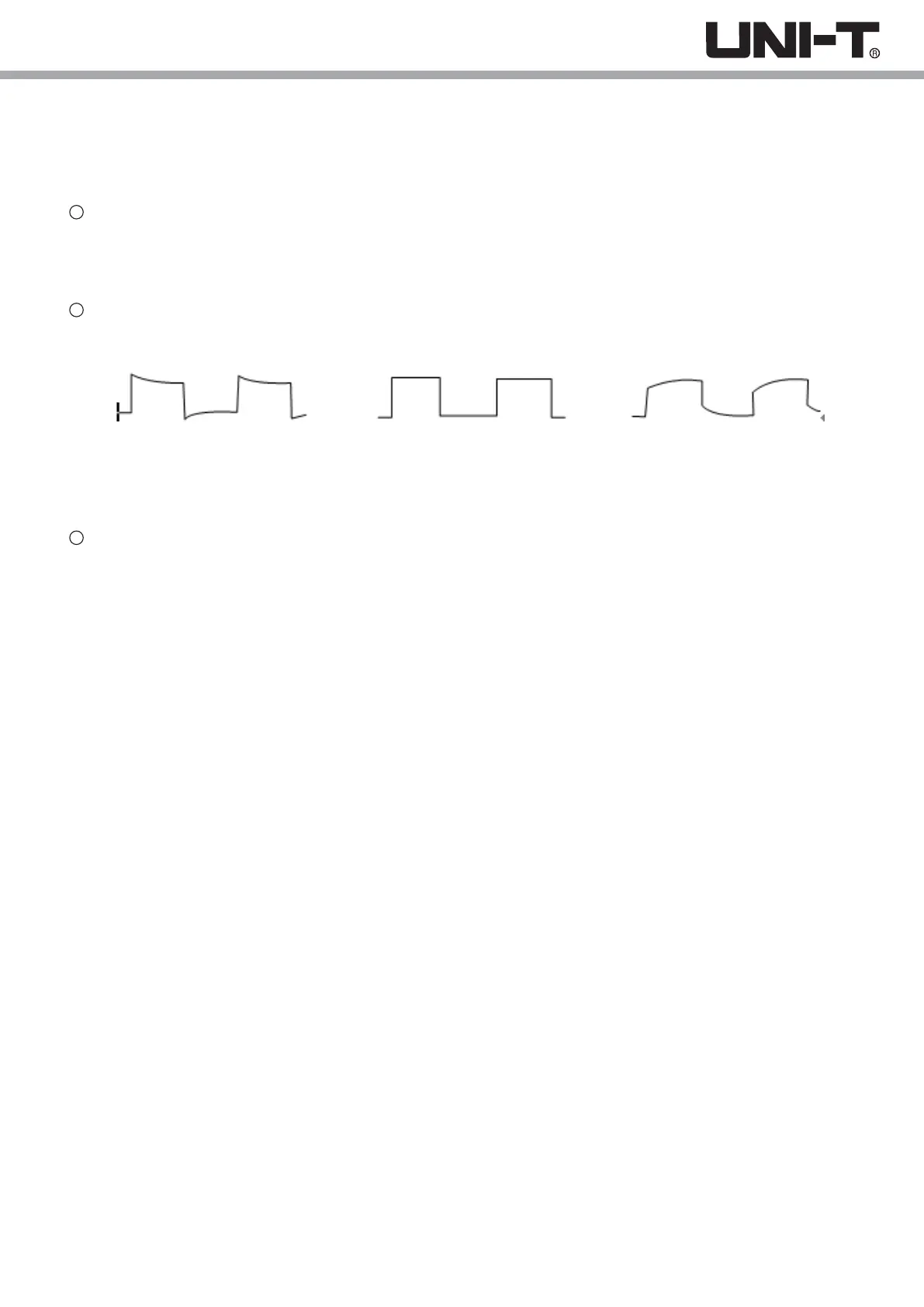
Observed waveforms.
Excessive Compensation Correct Compensation Insufficient Compensation
Picture 1-2 Probe compensation calibration
If the displayed waveform does not look like the above “correct compensation” waveform, use a non-metallic
screwdriver to adjust the probe’s variable capacitance until the display matches the "correct compensation"
waveform.
Warning: To avoid electric shock when measuring high voltage using the probe, please ensure that the
probe insulation is in good condition and avoid physical contact with any metallic part of the probe.
1
2
3
9
 Loading...